Assemble drive flange and fasten it by means of
disk and hex. head screws.
NOTE :
Wet contact area of disk with sealing compound !
Torque limit (M8/10.9) 34 Nm
Now, fix hex. head screws by means of lock plate.
( S ) Driver 5870 057 010
( S ) Handle 5870 260 002
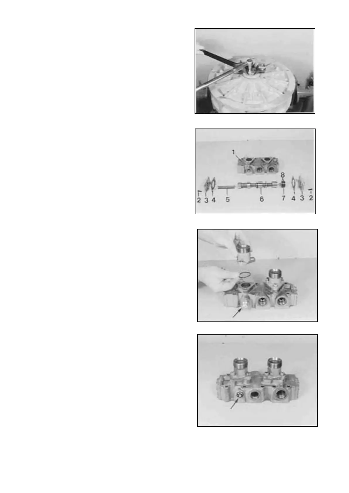
4.2.2 Pre-assemble and attach Retarder
valve
Install components according to the Figure on the
right.
1 = Case
2 = Hex. head screw
3 = Cover
4 = Gasket
5 = Compression spring
6 = Spool
7 = Spool
8 = Grooved rings
NOTE ;
Install grooved rings (8) with the sealing lip facing
the pressure chamber !
Fasten the two connecting pieces by means of
socket head screws.
Install temperature sensor (Arrow).
NOTE :
Install new O-Rings !
Torque limit (M8/8.8) 23 Nm
Install screw plug (Arrow).
NOTE ;
Install new O-Ring !
Transmission and Torque Converter SPC000007
Page 177
 Loading...