Introduce hollow shaft until contact is obtained.
Install two adjusting screws, replace 11a: gasket
and place compl. shift-control housing against gear
case until contact is obtained.
Fasten shift-control housing by means of socket
head screws and install output flange (Arrow).
Torque limit (Ml0/8.8 DIN 7984) 32 Nm
( S ) Adjusting screws (MI0) 5870 204 007
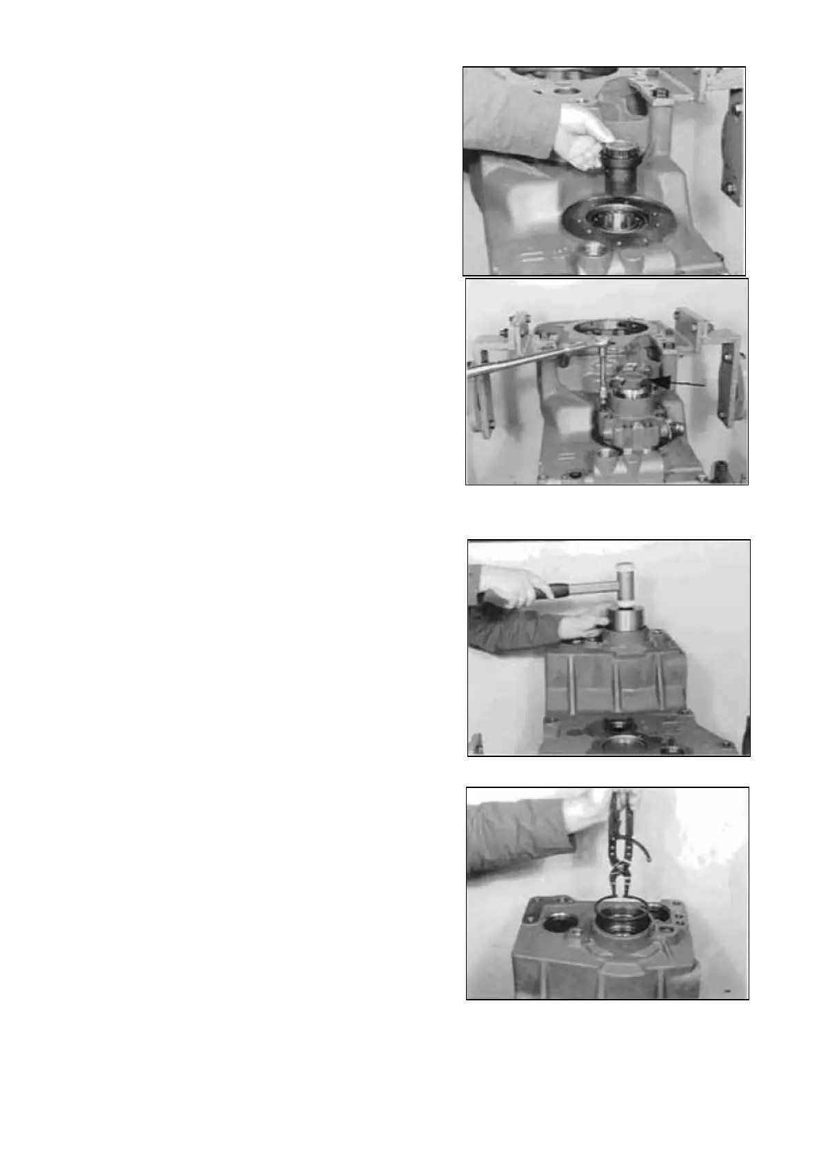
Tilt gear case 180°.
Drive differential assembly by careful tapping upon
the roller bearing downwards, until the exact contact
of the lower roller bearing (Figure 69) on the shift-
control housing (Figure 72) is ensured.
Adjust end play of the differential 0,4 0,6 mm (Figure
74 ... 76)
Squeeze in circlip.
( S ) Clamping pliers 5870 900 021
Transmission and Torque Converter SPC000007
Page 207