Machine description
4812158801_E.pdf 2018-04-03
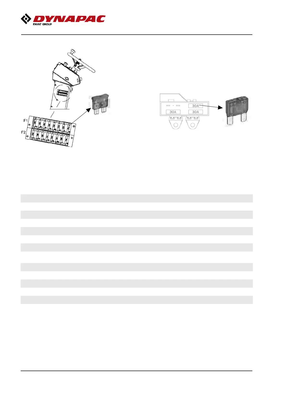
Fuses
Fig. Fuse boxes on the side of the panel.
The figure shows the position of the fuses.
There are two fuse boxes on the left side of the panel
(F1 & F2), as well as one fuse box by the battery
disconnector switch under the platform (F4).
Fig. Fuse box by the battery disconnector switch
F4
The table below gives fuse amperage and function. All
fuses are flat pin fuses.
Fuse box, upper (F1)Fuse box, upper (F1)
1
12V outlet 10A
5
Working lights 15A
1
12V outlet 10A
5
Working lights 15A
2
Direction indicator 10A
6
Driving lights 15A
2
Direction indicator 10A
6
Driving lights 15A
3
Cab heater 10A
7
Horn 10A
3
Cab heater 10A
7
Horn 10A
4
Rotating beacon 10A
8
Starting 5A
4
Rotating beacon 10A
8
Starting 5A
Fuse box, lower (F2)Fuse box, lower (F2)
1
Sprinkler, main circuit 15A
5
Indicator panel, Beeper, LEDs 10A
1
Sprinkler, main circuit 15A
5
Indicator panel, Beeper, LEDs 10A
2
Sprinkler control, Brake light, Reversing
alarm
10A
6
Measuring instrument 5A
2
Sprinkler control, Brake light, Reversing
alarm
10A
6
Measuring instrument 5A
3
Vibration, Brake, Start (VBS) 10A
7
Speed sensor, Tachograph 10A
3
Vibration, Brake, Start (VBS) 10A
7
Speed sensor, Tachograph 10A
4
Diesel engine 5A
8
Reserve
4
Diesel engine 5A
8
Reserve
Fuse box (F4)Fuse box (F4)
1
Main fuse, machine 30A
3
Main fuse, diesel engine 30A
1
Main fuse, machine 30A
3
Main fuse, diesel engine 30A
2
Main fuse, machine 30A
4
Reserve
2
Main fuse, machine 30A
4
Reserve
36