xLogic SuperRelay User’s Manual
68
Description of the function
The latching relay represents a simple binary memory logic. The output value depends on
the input states and the previous status at the output.
Logic table of the latching relay:
S R Q Remark
0 0 x Status unchanged
0 1 0 Reset
1 0 1 Set
1 1 0 Reset
When retentivity is enabled, the output signal corresponds with the signal status prior to
the power failure.
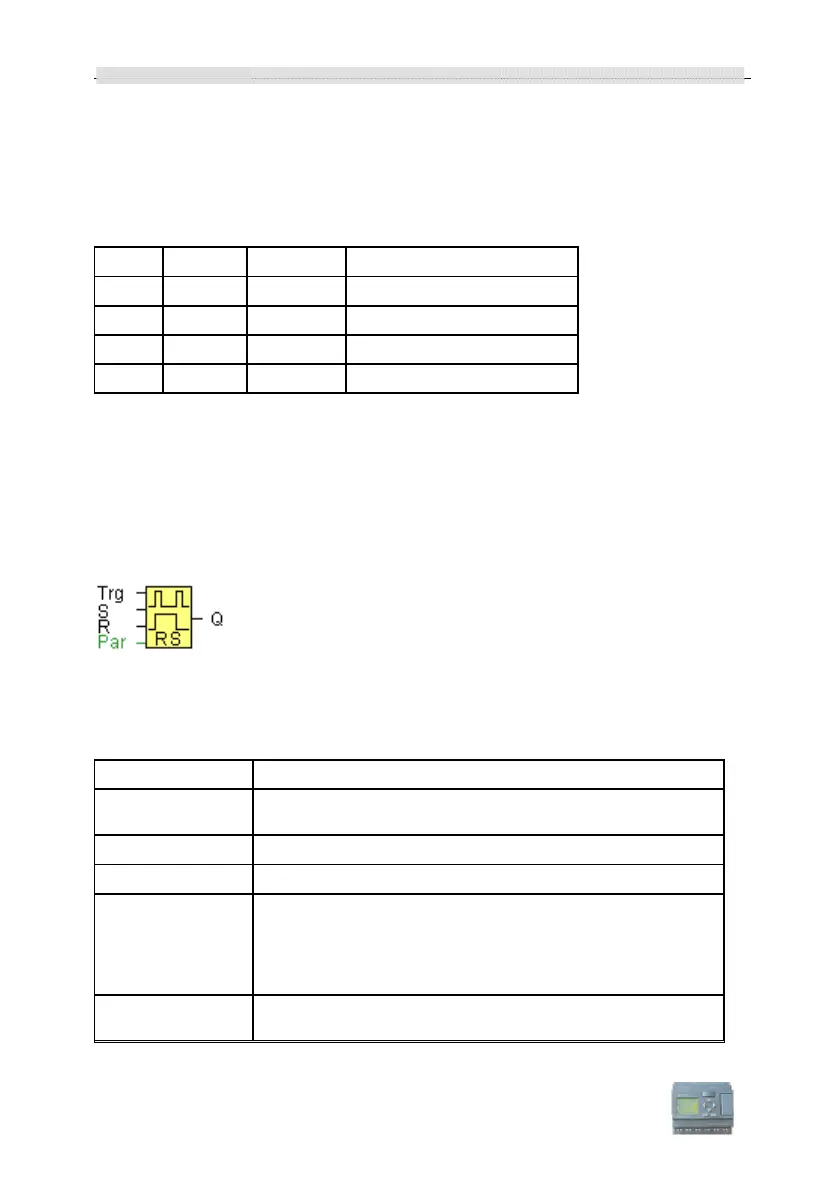
3.4.17 Pulse relay
Short description
The output is set and reset with a short one-shot at the input.
Connection Description
Input
You switch output Q on or off with a signal at input Trg
(Trigger) input.
Input
A one-shot at input S (Set) sets the output to logical 1.
Input
A one-shot at input R (Reset) resets the output to logical 0
Parameter
Selection:
RS (input R priority), or
SR (input S priority)
Retentivity set (on) = the status is retentive in memory.
Output
Q is switched on with a signal at Trg and is reset again at the
next Trg pulse, if both S and R = 0.