4.2.4
Start Control
I
»TRNC«
30% ⋅ FLA
t
MotorStart_Z02
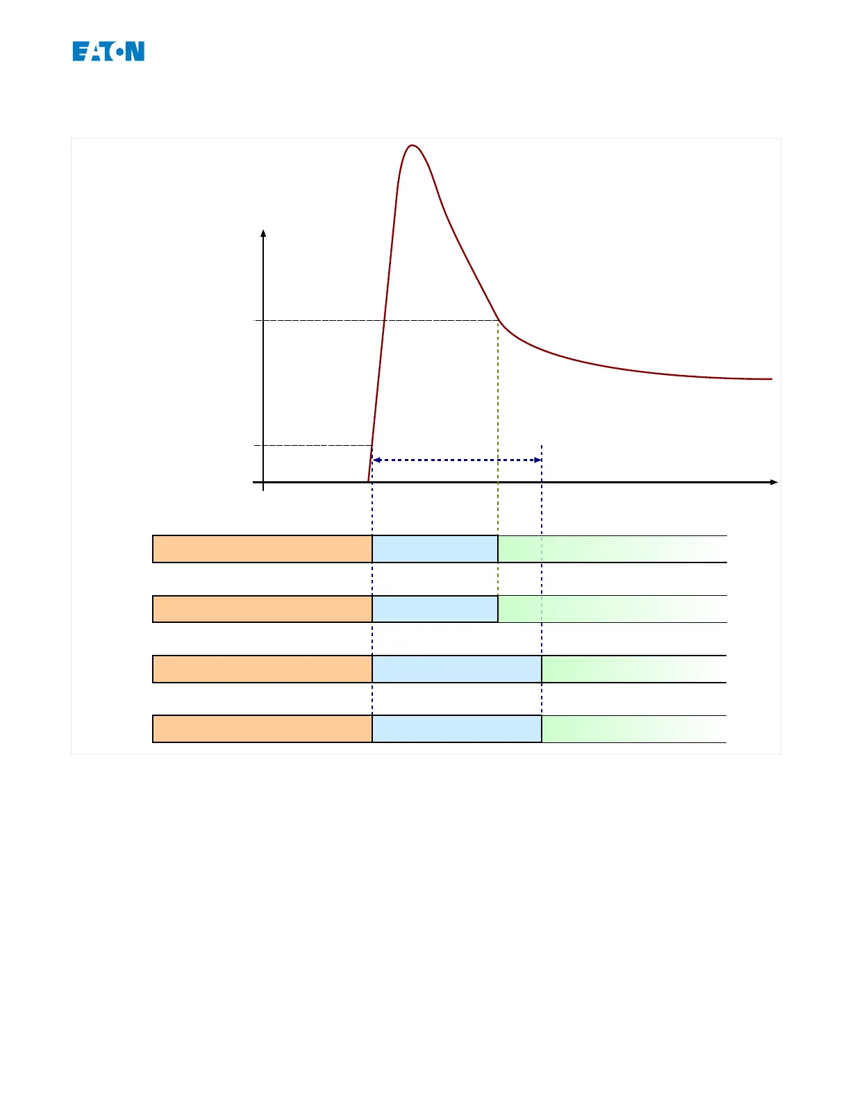
»TRN Criteria« = “TRN I”:
Stop Start Run
»TRN Criteria« = “TRN T or I”:
Stop Start Run
»TRN Criteria« = “TRN TIME”:
»TRNT«
RunStop Start
RunStop Start
»TRN Criteria« = “TRN T and I”:
The Start Control Module drawing shows an example of how the EMR-3MP0 reacts to a
normal operating-cycle current prole. Initially, the motor is stopped and the current is
zero. As long as the EMR-3MP0 is not in a trip state, it permits contactor energization by
closing its trip contact in series with the contactor. The contactor is energized by the
operator or process control system through a normal two-wire or three-wire motor control
scheme, external to the protective device.
The EMR-3MP0 declares a motor start when it senses a motor current that exceeds 30%
of the FLA setting, [System Para] »FLA«.
Meanwhile, the transition timer, [Protection Para / MStart / Start Control] »TRNT«, begins
to run.
The EMR-3MP0 also monitors the large starting current, noting when the current falls
below the transition level [Protection Para / MStart / Start Control] »TRNC«.
143www.eaton.comEMR-3MP0
4 Protective Elements
4.2 Motor Starting and Control Module

 Loading...


