2.2.11.1 RS485 - Modbus® RTU
WARNING!
Ensure the correct tightening torques.
HPT_Z55
0.3 Nm
2.65 lb⋅in
0.23 Nm
2.03 lb⋅in
1
X103
2
3
4
5
6
B(+)
A(-)
+5V
GND
560Ω
560Ω
120Ω
Protective Relay
HF Shield
E_F55
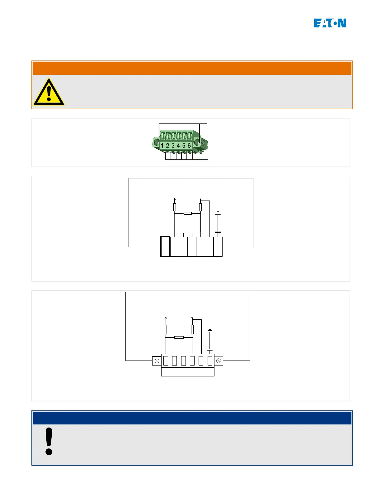
Fig. 26: Modbus® RTU – Terminal Marking
E_F56
64 5321
R1
R2
R1
+5V
GND
R1 = 560Ω
B(+)
A(-)
Protective Relay
HF Shield
R2 = 120Ω
Fig. 27: Modbus® RTU – Pin Assignment
NOTICE!
The Modbus® connection cable must be shielded. The shielding has to be
xed at the
screw that is marked with the ground symbol at the rear side of the device.
The communication is Half-Duplex.
94 www.eaton.com EMR-3MP0
2 Hardware
2.2 EMR-3MP0 – Installation and Wiring

 Loading...


