4.15.2
Trip Bypass Functionality
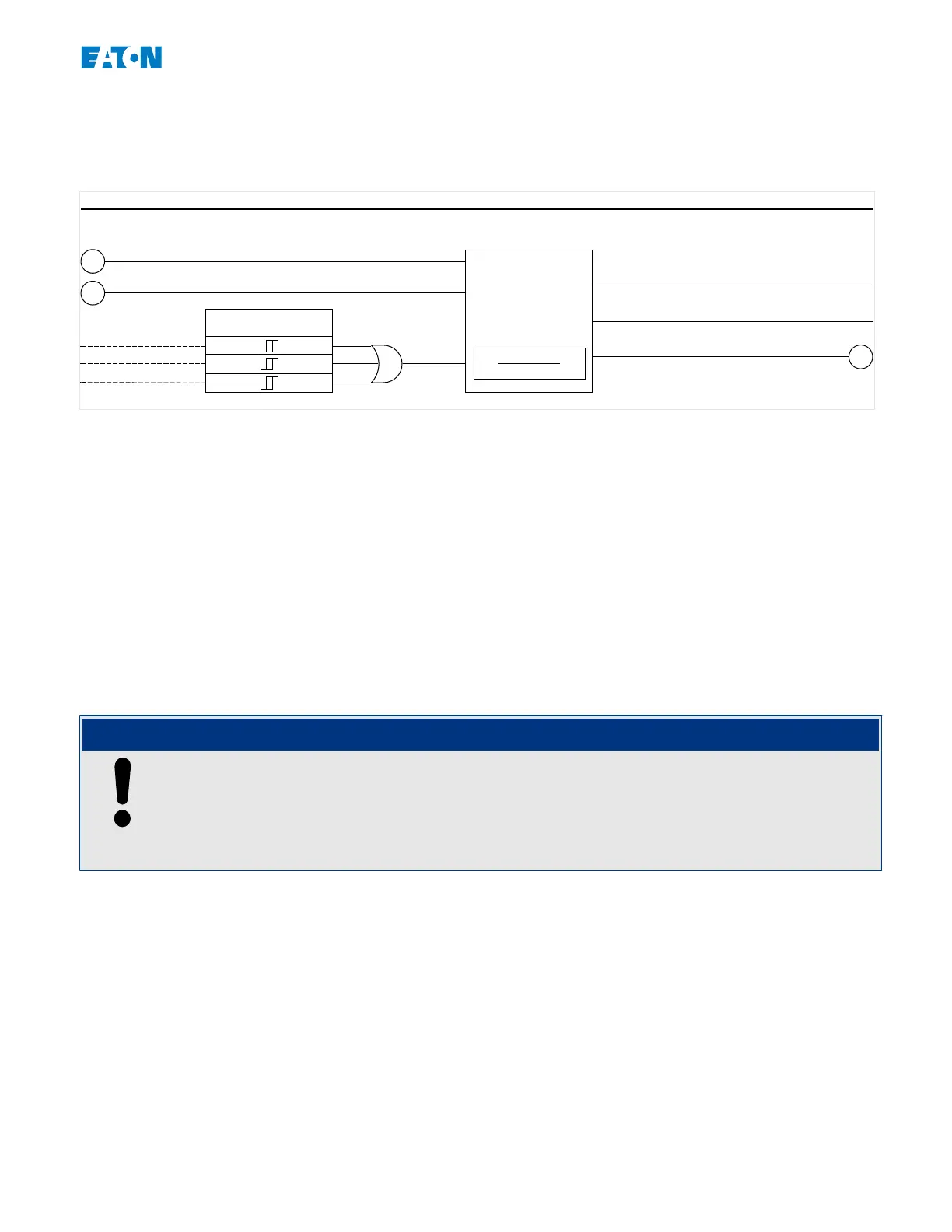
Breaker Failure Protection for devices that oer current measurement
Trip Bypass
CBF_E91
2
51
14
Please Refer to Diagram: Blockings
(Element is not deactivated and no active blocking signals.)
Trip Bypass . Trip
Φ
IA
IB
IC
Trip Bypass . Pickup
Trip Bypass . Waiting for Trigger
1 s
0
0.1⋅In
OR
Prot . Trip
4.15.3
Trip Bypass Commissioning Example
Object to Be Tested:
Test of the »Trip Bypass« module.
Necessary Means:
• Current source;
• Ammeter; and
• Timer.
NOTICE!
When testing, the applied test current must always be higher than the device-internal
threshold 0.1⋅In.
If the test current falls below the threshold while the breaker is in the “O” position, no
pickup is generated.
Procedure (Single-Phase):
For testing the tripping time of the »Trip Bypass« module, a test current has to be higher
than the threshold value of one of a current protection module. The »Trip Bypass« trip
delay can be measured from the time when General Trip signal »Prot . Trip« becomes
active, to the time when the »Trip Bypass . Trip« signal becomes active.
To avoid wiring errors, make sure the breaker in the upstream system switches o.
The time, measured by the timer, should be in line with the specied tolerances.
Successful Test Result:
191www.eaton.comEMR-3MP0
4 Protective Elements
4.15 Trip Bypass [50BF/62BF]

 Loading...


