1.1.2.1 Symbols in Function Diagrams
E_E05
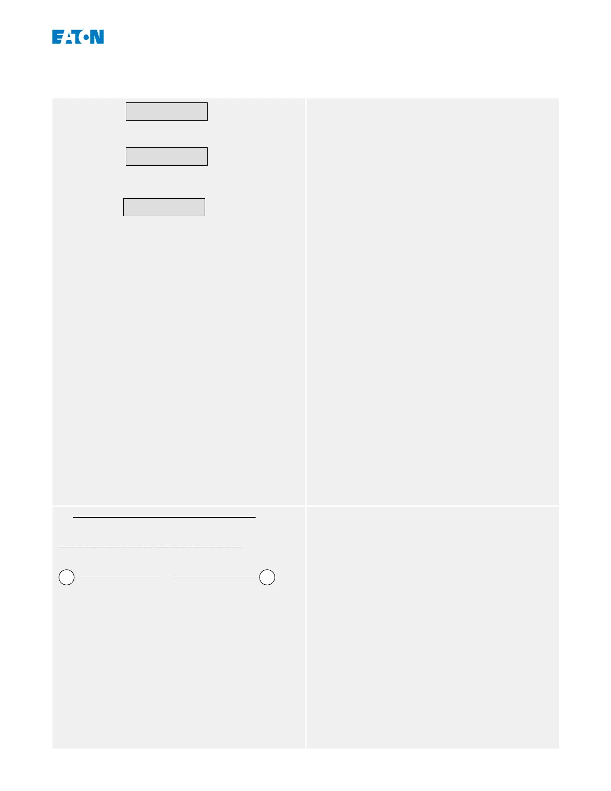
50P[1] .
Pickup
Name .
Pickup
delta phi - Mode
System Para
Setting Values
The upper box in the diagram on the left is the
usual symbol of a setting value in a function
diagram. The setting name is specied by its
module and parameter name, separated by a
dot “.” one from the other.
Second example: Thanks to the high degree of
modularisation in E‑Series protection devices,
the logic depicted in some function diagrams is
often valid for several modules. In these cases,
only a symbolic module name, for example:
“Name”, is given. In the heading part of the
diagram, the meaning of “Name” is specied as
a list of modules to which the diagram applies.
In rare cases it is necessary to also specify the
menu path (or at least the top-level menu item),
because it would be too inconvenient to specify
this particular setting only based on module
name and parameter name. In the third
example, the setting »delta phi - Mode« is
marked as a Field Parameter (i. e. to be found
within menu branch [System Para]).
Another remark: All diagrams in this document
show a small label, in this case: “HPT_Y05”. This
is the diagram name, i. e. a unique identier for
the diagram. Of course, this is not a setting
name, nor any other part of the depicted logic.
All function diagrams have an identier with the
characters “_E”.)
HPT_Y06
Name . Pickup Vector Surge
VA
1
2
Prot. Active Name . Active
Input and Output Signals
A binary (output) signal is shown on top.
Below the dashed line indicates a measured
value (i. e. an analog signal).
Bottom row, left: Numbered input signal; right:
numbered output signal: From the technical
point of view, there is no dierence to “normal”
(non-numbered) signals. But these signals
appear in several dierent diagrams, and the
numbering helps to identify and locate them
across the Technical Manual.
Therefore all encircled numbers appearing “on
the right side” (i. e. as an output signal) of a
diagram are listed as part of the Index chapter,
17www.eaton.comEMR-3MP0
1 EMR‑3MP0 Motor Protection Relay
1.1 Comments on the Manual

 Loading...


