EBS-6100 Printer User's Manual
Paragraph 4 - Operating the Printer
EBS
Ink-Jet Systems
®
28
20070529#20.5
the correct measurement phasing signal
2
. Therefore vital parameters are measured within the
print head continuously. The settings of these parameters form the so called print head
status and are shown on the terminal display in the printer status window.
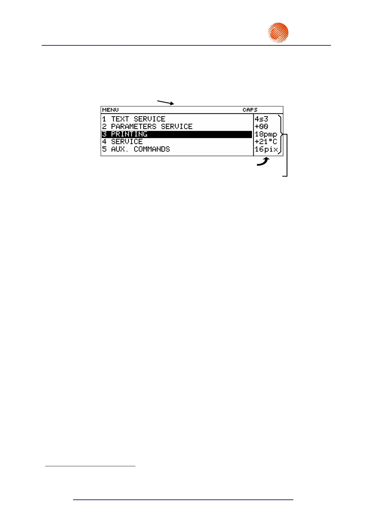
A sample head status is given below.
Graphic display
Printer status window
Head status block
Fig. 4.3.1.
The characters of the status block have the following meaning:
The first digit on the first line indicates the quality of phasing - it can vary between 2 and
6 (with 4 being the optimum). Frequent fluctuations of the quantity from the optimum
indicate that the unit is tuned improperly. A question mark
? which may appear at this
position from time to time means erroneous measurement of phasing. If the mark is
displayed frequently or continuously, this means that the unit is not tuned properly,
especially within the head, and may lead to a phasing error and an alarm.
The second digit on the first line (one character) indicates the head operation mode. The
head can be in one of the following four modes:
r (restart) the head operation has been restarted (no phasing, the printing
disabled, the READY lamp on the internal panel is off),
s (stop) the head is ready to start the printing (phase and ink viscosity are
measured, the READY lamp on the internal panel generates steady light),
p (print) the head performs the operation of printing as the result of the
START PRINT or PRINT SWITCH commands (high voltage is turned on, phase
and viscosity are measured, the READY lamp and the HV lamp on the internal
and external panel generate steady light),
v (service) the head is in service mode and enables the user to perform service
operations (phase and ink viscosity are measured, no alarm is indicated if a
phasing error occurs).
The third digit on the first line (one character) indicates the number of the best phase
determined during the phasing process. It can vary between 0 and 7. Variations in
magnitude every now and again at few-second intervals indicate that ink parameters vary
too quickly (and these are allowed only for a short period after the unit has been switched
on). Changes by ±1 are normal for this parameter.
Three positions on the second line are used to show ink viscosity and other information.
The viscosity is given in relation to its rated value of +00. Positive numbers indicate that
viscosity levels are higher than the rated value, with negative numbers the viscosity is
smaller than the rated value. The correct value ranges between +15 and -05. Two other
characters such as > (<) can be displayed at the position in emergency cases: when ink
viscosity rises (drops) above (below) the value of 99.
The following messages may also occur on the second line:
Per phasing error.
2
Phasing - automatic process of controlling the charging of ink droplets. The breaking point at which a continuous ink jet
breaks into droplets varies slightly with time. Therefore the control system needs to update time relations between
the charging and breaking of an ink jet into droplets on an on-going basis.