EBS-6100 Printer User's Manual
Paragraph 4 - Operating the Printer
EBS
Ink-Jet Systems
®
68
20070529#20.5
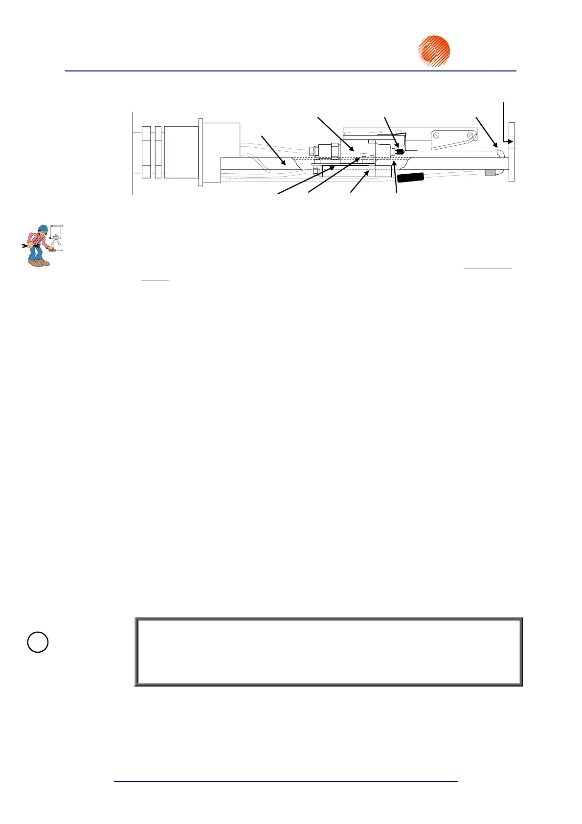
Head – side view
Slide
Gun
Nozzle Gutter
Plate Screw V3
Screw V4 Slide
Head
window
Fig. 4.4.4.8.1.
The path of the ink jet in relation to the immovable gutter can be adjusted with two V
screws. If you drive in screw V3 clock wise, the jet path goes down in the gutter. If
you drive in screw V4, the jet path goes up in the gutter. Make the adjustment with
both screws at the same time so that the gun plate bends. The screws need to be
locked in their positions after the adjustment, i.e. the screw V3 driven into the head
slide should rest with its end on the plate, and the screw V4 going through the plate
and driven into the slide should rest with its head on the plate.
Adjust the ink jet path (with the V screws) so that distances X and Y shown in
Fig. 4.4.4.8.3 are the same. The adjustment is made with the SET INK STREAM
command.
The SET INK STREAM command is a service command for adjusting the ink-jet path
in the vertical direction for various high voltage settings so that unused ink drops fall
into the gutter. The path adjustment in the vertical direction is needed each time
the high voltage setting is modified or when the nozzle, the gutter, the gun or
components of the gun suspension system are replaced or the position of head
components needs to be re-adjusted.
The execution of the SET INK STREAM command involves the following steps:
1) Switch the printer on and wash the head (especially the gutter) carefully.
2) Wait until the READY lamp on the internal panel comes on.
3) Create a text file (for each of the maximum heights of 7, 16, 25 or 32 dots at the
best) and set print parameters with the PRINTING PARAMETERS command.
4) Select the START PRINT command to print the previously created text file, and
then select the QUICK STOP command. The objective of this operation is to
make the print parameter settings effective before the SET INK STREAM
command is selected.
5) Check whether the ink jet falls into the middle of the gutter horizontally.
6) Place the head in the microscope holder to observe the ink jet falling down into
the gutter (see Fig. 4.4.4.8.2). Plug the stroboscope connector into the female
connector ST15 on the head control card, which is available on opening the
upper door (with the external panel on it) - see Fig. 4.4.4.8.4. When the
connector is plugged in properly, the stroboscope LED comes on. Reverse
connection does not cause any damage.
NOTE:
If no microscope is available, you can follow the steps below by observing the ink jet
falling into the gutter against a background, whose colour contrasts with the colour of
ink. A magnifying glass can also be used but it is not likely to contribute to accurate
adjustment.
EBS
!