417101774_EMP_KKS_E60_E.doc - 10 - Rev. 8-03.10
5.3 Indicators / Controls / Jacks
5.3.1 EMP KKS E60 and EMP KKS E60
PLUS
versions
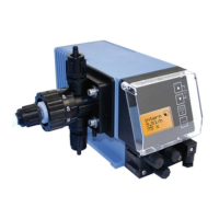
Pos. Description
1 Control knob for setting the
stroke length
2 Menu/Exit,
up arrow key
3 Menu/Exit,
down arrow key
4 Start/Stop key
(Enter function)
5 Test key
6 Graphical display
Fig. 5.5
1
2
6
3
4
5
II
III
I
I
Pos. Description
I input for low-level advance warning and empty report (see 7.2.2 & 14.5)
II input for pulse- / standard signal and metering lock (see 7.2.3 & 14.5.2)
III and empty report, fault report and stroke signal (see 7.2.4 & 14.5.3)
IV mains power supply (see 7.2.5)
5.3.2 “Dongle box” ports
Pos. Description
V input for oval gear meter
VI connection for pulse input to EMP pump
(input II)
VII input for batch pulse and metering lock
VIII input for pulse, standard signal input and
metering lock
Fig. 5.6
I
II
III

 Loading...