417101774_EMP_KKS_E60_E.doc - 9 - Rev. 8-03.10
5 Setup
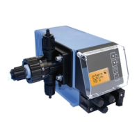
5.1 EMP KKS E60
Fig. 5.1 Fig. 5.2
6
5
4
3
1
A
2
5
1
5.2 EMP KKS E60
PLUS
Fig. 5.3 Fig. 5.4
B
B
6
5
43
1
Pos. Description
1 Suction valve (connection on the suction side)
2 Diaphragm breakage sequence
3 Venting connection (refeeding into the container)
4 Stroke length adjustment
5 Pump head
6 Pressure valve (connection on the pressure side)
A Rail for connecting the dongle box
B Dongle box
Flow direction of the metering medium

 Loading...