Components
3Liebert
®
CW
™
System Design Manual
1.2 Components
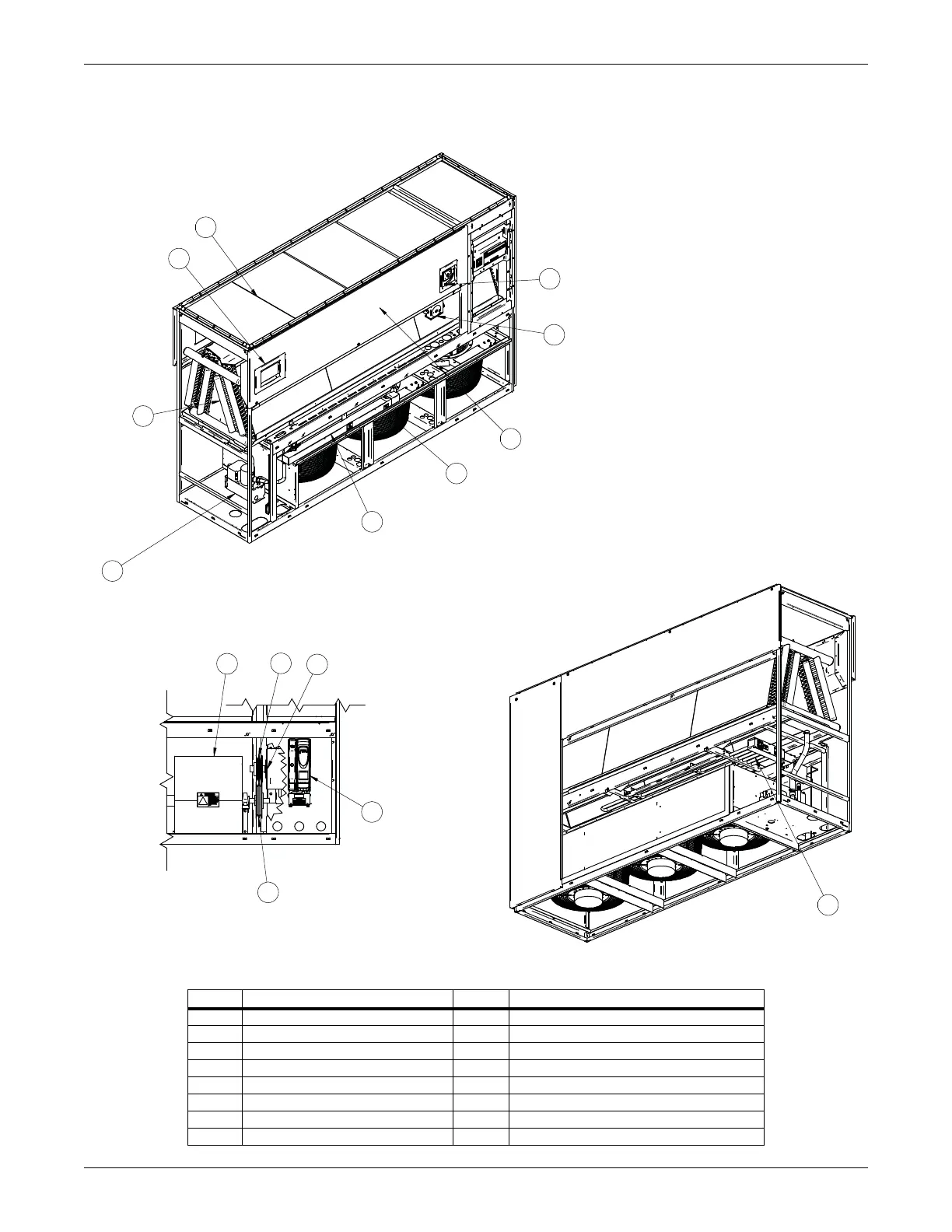
Figure 1-1 Downflow model component locations
Item Description Item Description
1 iCOM control display 9 Infrared humidifier (optional)
2 Electric box 10 Reheat (optional)
3 Filters 11 Disconnect (optional)
4 Coil 12 Condensate pump (optional)
5 Motor 13 Variable-frequency drive (optional)
6Blower 14EC fans
7 Fan pulley 15 Smoke detector (optional)
8 Motor sheave and belts
Optional EC Fan Configuration
Front View
3
10
Rear View
Ships loose for field installation
on CW026-CW060 units.
1
11
15
14
9
12
4
2
5
6
7
8
13
Optional Forward-Curved Blower View
DPN002869
Rev. 3
Optional EC Fan Configuration