Electrical Field Connections—Upflow Models
75 Liebert
®
CW
™
System Design Manual
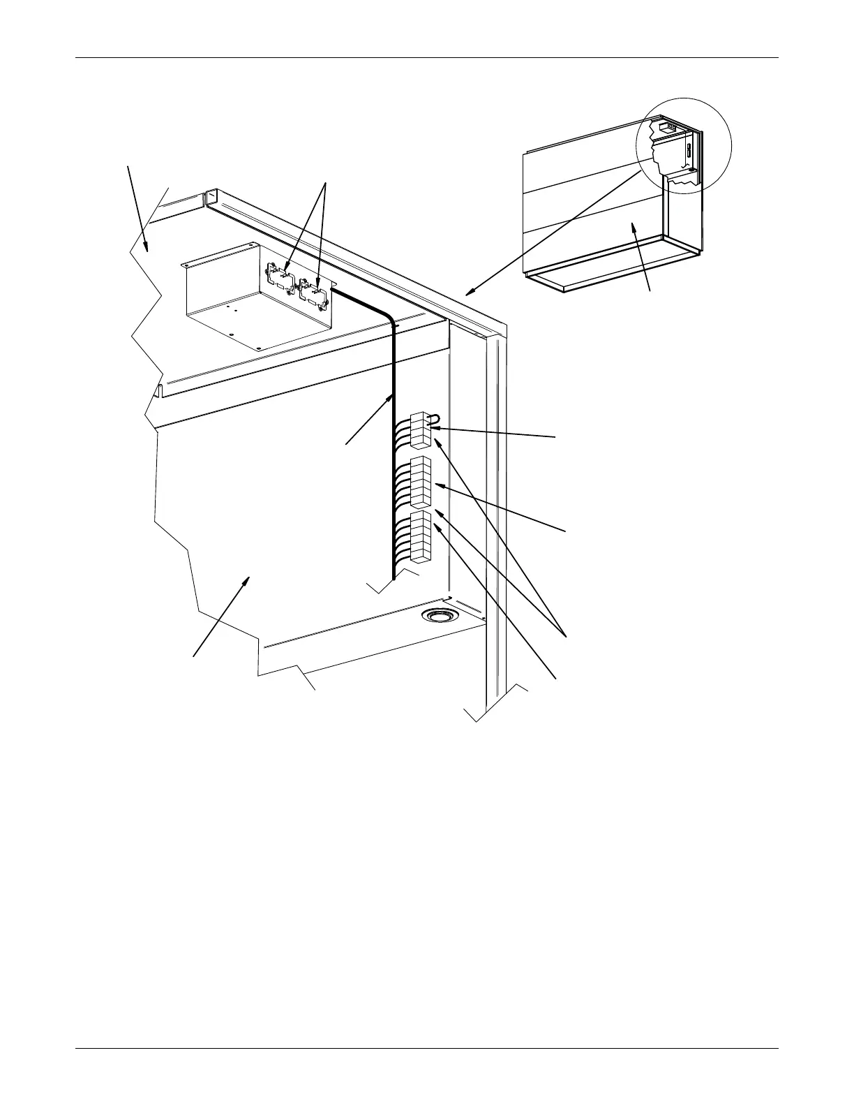
Figure 6-7 Electrical field connections (low voltage), upflow, CW026 – CW084
NOTE: REFER TO SPECIFICATION SHEET FOR FULL LOAD
AMP. AND WIRE SIZE AMP. RATINGS
3
7
3
8
2
4
5
0
9
1
9
2
9
3
5
1
5
5
5
6
Intellislot Housings.
Optional Monitoring and
Communication cards inserted here.
Smoke detector alarm connections.
are #91-comm., #92-NO, and #93-NC.
terminals from optional smoke detector
remote alarm circuits. Factory wired
Field supplied 24V. Class 2 wire to
Factory Wiring
Back of Electric Box
Back of Unit
Underside of Unit Top
7
5
7
6
9
4
9
5
9
6
9
7
Common Alarm Connections.
Field supplied 24V. Class 2
wiring to common alarm
terminals 75 + 76 which are
factory connected to common
alarm relay (R3). Optional
extra common alarm terminals
94+95 and 96+97 are also
connected to R3 relay.
24V. Class 2 wire for special alarms.
Field supplied
Special alarm connections.
Remote unit shutdown.
field supplied 24V Class 2 wire.
having a minimum 50VA rating. Use
37 + 38 with normally closed switch
jumper between terminals
Replace existing
DPN003201
Pg. 1 Rev. 1