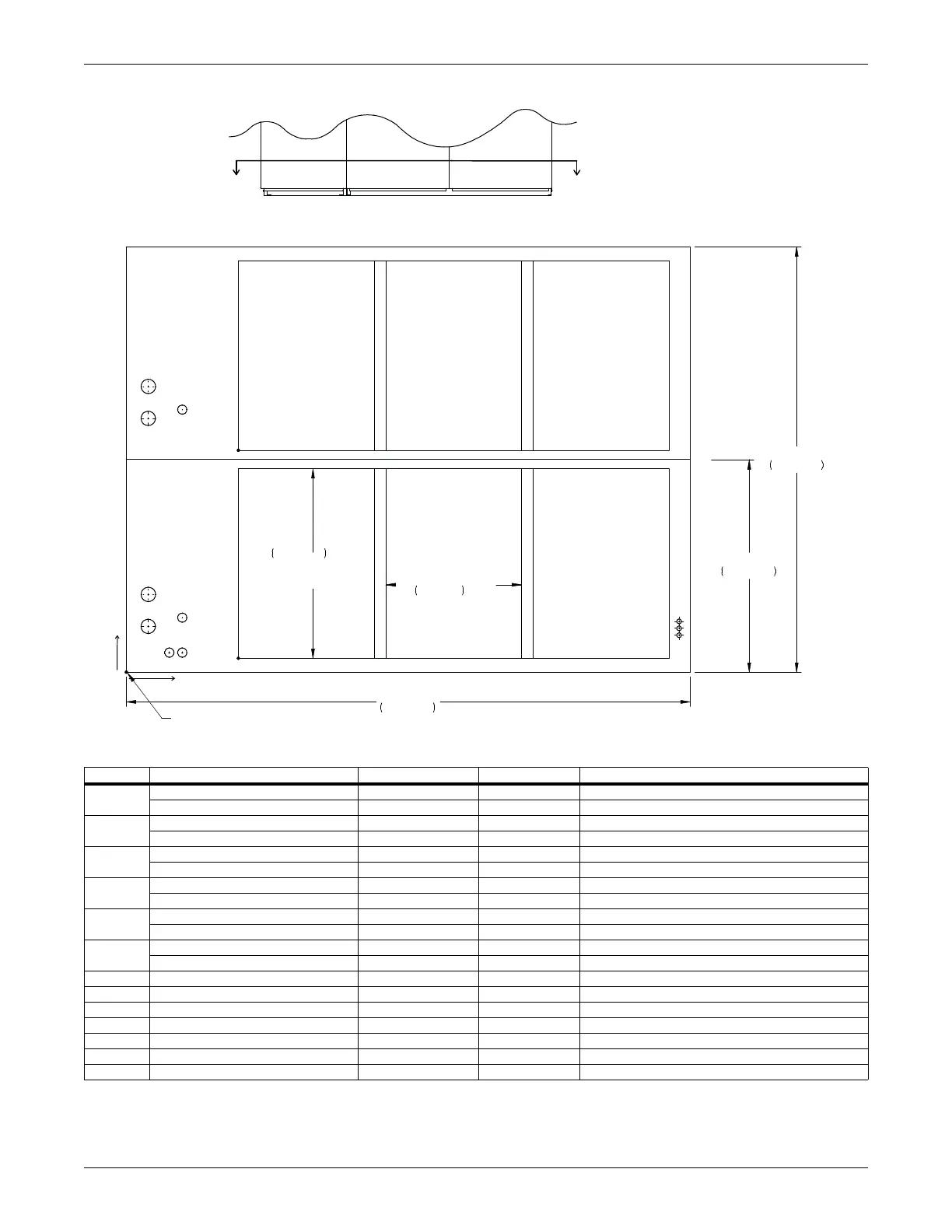
Piping Connections—Downflow Models with EC Fans
61 Liebert
®
CW
™
System Design Manual
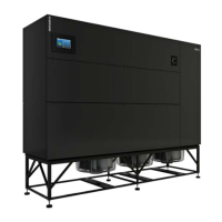
Figure 5-9 Primary connection locations, downflow, CW300 and CW400 with EC fans
Point Description X, In. (mm) Y, In. (mm) Connection Size / Opening, In. (mm)
CD 1
Condensate Drain * 12 (305) 12 (305) 1-1/4” FPT
W/ Optional Pump 12 (305) 12 (305) 1/2” Cu Sweat
CD 2
Condensate Drain * 12 (305) 57 (1449) 1-1/4” FPT
W/ Optional Pump 12 (305) 57 (1449) 1/2” Cu Sweat
CWS1
2-way Chilled Water Supply 5 (127) 10 (254) 3-1/8”
3-way Chilled Water Supply 5 (127) 10 (254) 3-1/8”
CWS2
2-way Chilled Water Supply 5 (127) 55 (1397) 3-1/8”
3-way Chilled Water Supply 5 (127) 55 (1397) 3-1/8”
CWR1
2-way Chilled Water Return 5 (127) 17 (432) 3-1/8”
3-way Chilled Water Return 5 (127) 17 (432) 3-1/8”
CWR2
2-way Chilled Water Return 5 (127) 62 (1575) 3-1/8”
3-way Chilled Water Return 5 (127) 62 (1575) 3-1/8”
E1 Electrical Conn. (High Volt) 9 (229) 4 (102) 2"
E2 Electrical Conn. (High Volt) 12 (305) 4 (102) 2"
LV1 Electrical Conn. (Low Volt) 119-1/2 (3035) 11 (279) 7/8”
LV2 Electrical Conn. (Low Volt) 119-1/2 (3035) 9-1/2 (241) 7/8”
LV3 Electrical Conn. (Low Volt) 119-1/2 (3035) 8 (203) 7/8”
B Front Blower Outlet 24-1/2 (622) 3 (76) 93" x 41" (2362mm x 1041mm)
C Rear Blower Outlet 24-1/2 (622) 48 (1219) 93" x 41" (2362mm x 1041mm)
* Field pitch Condensate Drain line a minimum of 1/8” (3.2 mm) per foot (305 mm). All units contain a factory-installed condensate trap. Do
not trap external to the unit. Drain line may contain boiling water. Select appropriate drain system materials. The drain line must comply
with all local codes.
FRONT VIEW
FRONT OF UNIT
SECTION A-A
NOTE: Drawing not to scale.
Tolerance on
all piping dimensions
is ± 1/2" (13mm).
ALL DIMENSIONS FROM
FRONT CORNER OF UNIT
INCLUDING PANELS
E2
CD1
B
LV1
LV2
O
X
Y
CWS1
CWR1
41"
1041mm
TYP
AIR DISCHARGE
AREA
46"
1168mm
122"
3099mm
LV3
E1
29 3/8"
746mm
TYP
AIR DISCHARGE
AREA
C
CD2
CWS2
CWR2
92"
2337mm
DPN002434
Rev. 1
AA