Piping Connections—Upflow Models
65 Liebert
®
CW
™
System Design Manual
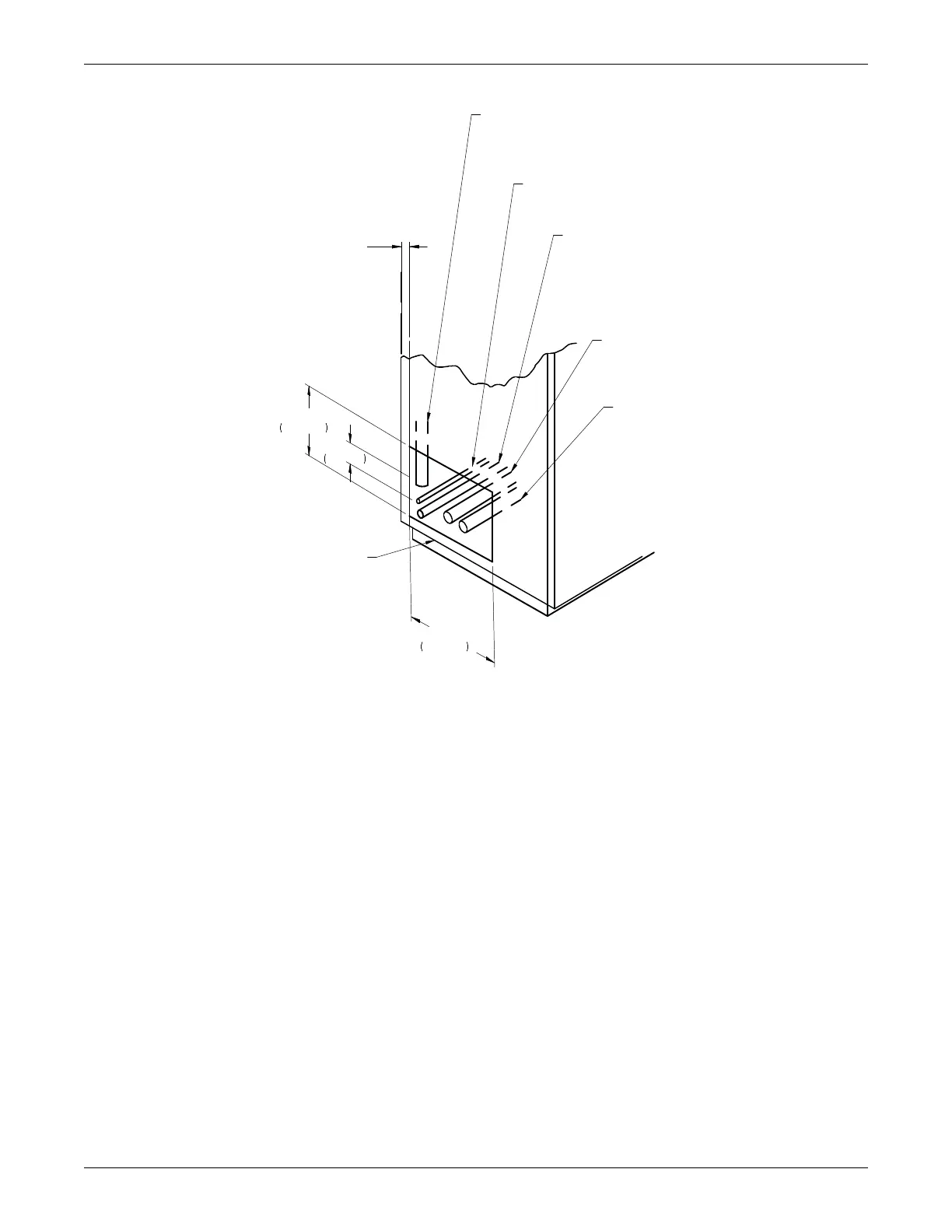
Figure 5-13 Piping connections, upflow, CW106 and CW114
NOTE: Install all piping
per local codes.
UNIT FIELD PIPING LOCATIONS
Piping stubbed out inside unit end compartment for field
connection through 13" x 6-1/2" (330 x 165mm) opening as
shown. Piping may also exit through bottom of end
compartment by field cutting an opening in a suitable
location.
A
- Chilled Water Supply Line.
2-5/8" O.D. CU on 3 way
front return units only.
1/4" OD CU Humidifier Water
Supply Line.
UNIT LEFT
END PANEL
1" (25mm) REAR PANEL
Condensate Drain. Field pitch a min. of
1/8" (3mm) per ft. (305mm). 1-1/4" NPT for units without
a factory installed condensate pump. 1/2" OD CU for
units with factory installed condensate pump. Do not
install an external trap.
B
- Chilled Water Return Line.
2-5/8" O.D. CU
3"
76mm
7 1/2"
190mm
13"
330mm
A
- Chilled Water Supply Line
2-5/8" O.D. CU on all units
except 3 way front return.
DPN001669
Rev. 1