Piping Connections—Downflow Models with EC Fans
57 Liebert
®
CW
™
System Design Manual
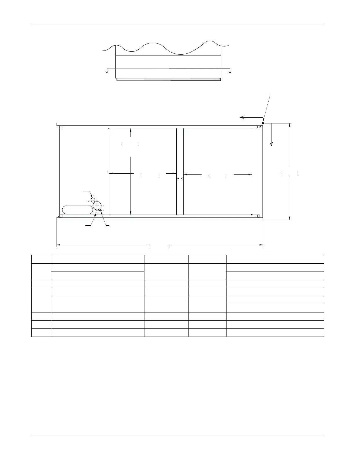
Figure 5-5 Primary connection locations, downflow, CW051 and CW060 with EC fans
Point Description X, in (mm) Y, in (mm) Connection Size / Opening, in (mm)
CD
Condensate Drain*
61 (1550) 27-3/4 (705)
3/4 (19) FPT
w/Optional Condensate Pump** 1/2 (13) Cu Sweat
HUM Humidifier Supply Line 58-3/8 (1484) 31-7/16 (799) 1/4 (6) Cu Sweat
CWP
Chilled Water Piping Slot (Center) 66-1/2 (1690) 31-1/4 (794) 11 x 3 (279 x 76)
Supply & Return Piping Diameter — —
CW051: 1-5/8 (41)
CW060: 2-1/8 (54)
HV High Volt Electrical Connection 59-1/2 (1512) 29-3/4 (756) 3 (76)
LV Low Volt Electrical Connection 59-1/2 (1512) 32 (813) 7/8 (22)
B Blower Outlet Opening 4 (101) 33 (838) 51 x 31 (1295) x 787)
* Field pitch Condensate Drain line a minimum of 1/8” (3.2 mm) per foot (305 mm). All units contain a factory installed condensate trap. Do
not trap external to the unit. Drain line may contain boiling water. Select appropriate drain system materials. The drain line must comply
with all local codes.
** Optional Condensate Pump to be field installed under unit.
FRONT VIEW
NOTE: Drawing not to scale.
Tolerance on
all piping locating
dimensions
± 1/2" (13mm).
FRONT OF UNIT
SECTION A-A
X
Y
ALL DIMENSIONS FROM
RIGHT REAR CORNER OF UNIT
WITH PANELS ASSEMBLED
0
CD
LV
HV
CWP
35"
889mm
74"
1880mm
31"
787mm
TYPICAL AIR
DISCHARGE AREA
24 1/4"
615mm
AIR DISCHARGE
AREA
24 1/2"
623mm
AIR DISCHARGE
AREA
B
HUM
DPN002035
Rev. 2
AA