Safety
information
Product
information
Mechanical
installation
Electrical
installation
Getting
started
User Menu A Commissioning
Advanced
Parameters
Diagnostics Optimization CT MODBUS RTU Technical Data
E300 Design Guide 47
Issue Number: 1
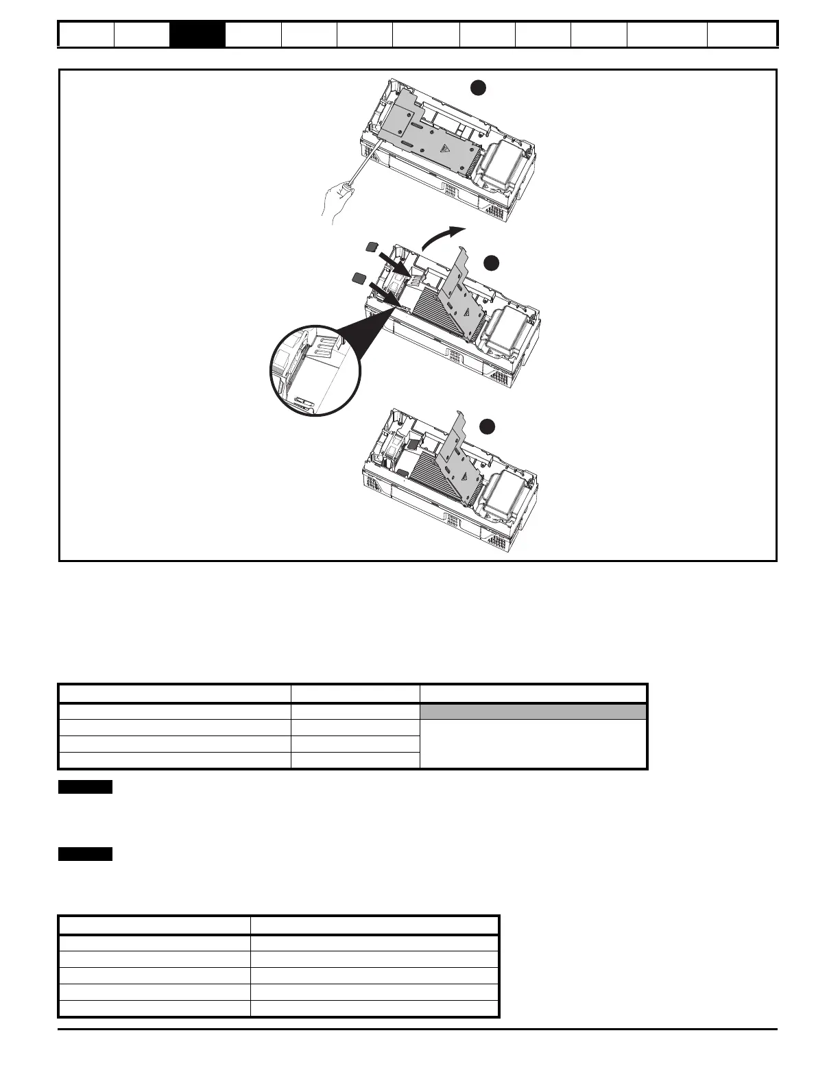
Figure 3-25 Installation of high IP insert for size 5
1. To install the high IP insert, firstly place a flat head screwdriver into the slot highlighted (1).
2. Pull the hinged baffle up to expose the ventilation holes, install the high IP inserts into the ventilation holes in the heatsink (2).
3. Ensure the high IP inserts are securely installed by firmly pressing them into place (3).
4. Close the hinged baffle as shown (1).
To remove the high IP insert, reverse the above instructions.
The guidelines in Table 3-6 should be followed.
Table 3-6 Environment considerations
A current derating must be applied to the drive if the high IP insert is installed. Derating information is provided in section 2.4.2 Power and current
ratings (derating for switching frequency and temperature) on page 14.
Failure to do so may result in nuisance tripping.
When designing an IP65 (NEMA 12) enclosure (Figure 3-20 Example of IP65 (sizes 3 to 7) (NEMA 12) through-panel layout on page 43),
consideration should be made to the dissipation from the front of the drive.
Table 3-7 Power losses from the front of the drive when through-panel mounted
Environment High IP insert Comments
Clean Not installed
Dry, dusty (non-conductive) Installed
Regular cleaning recommendedDry, dusty (conductive) Installed
IP65 compliance Installed
Frame size Power loss
3 ≤ 50 W
4 ≤ 75 W
5 ≤ 100 W
6 ≤ 100 W
7 ≤ 204 W

 Loading...
