Emerson Process Management GmbH & Co. OHG 4-13
X-STREAM XE
Instruction Manual
HASXEE-IM-HS
10/2012
4
Installation
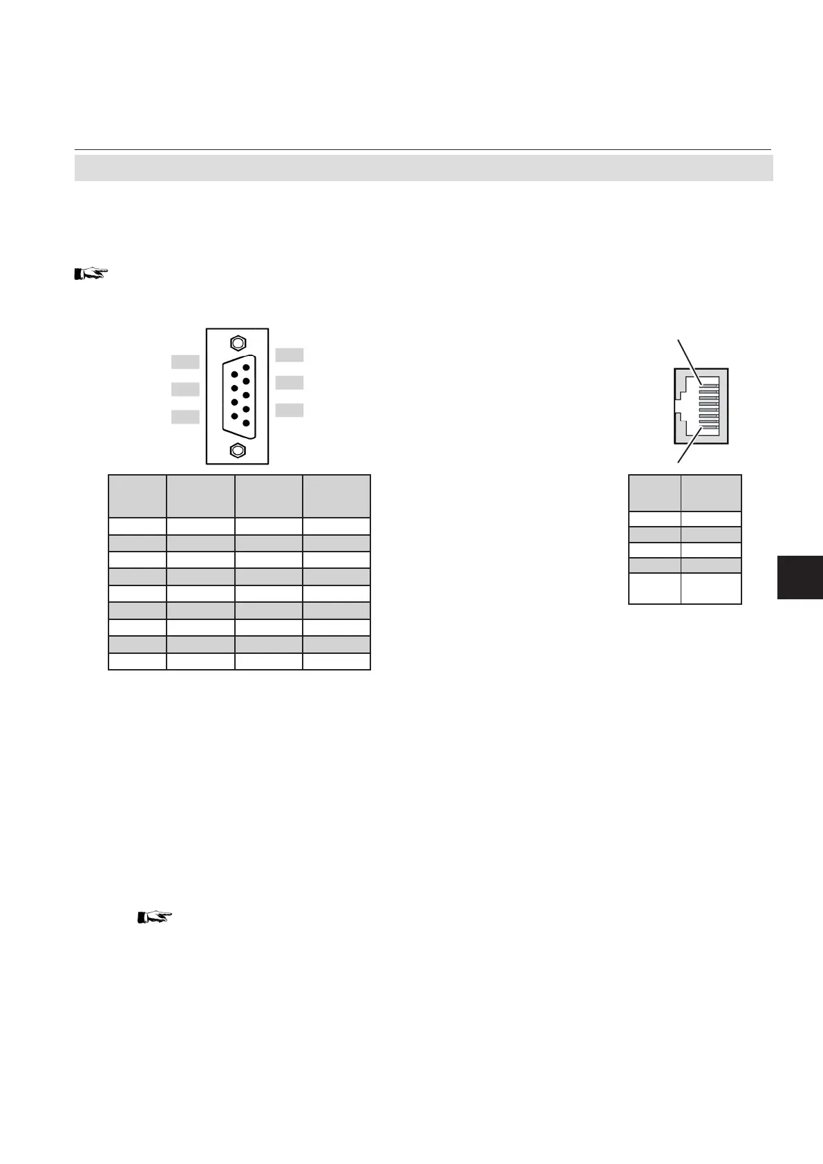
4.6.1 Installation - X-STREAM XEGK, X-STREAM XEGP
Fig. 4-8: Plug X2 - Serial Interface
Serial interface
For specications and notes on control, see
chapter 7
Pin 1
Pin 8
Ethernet connector
Pin no.
Signal
1 TX+
2 TX-
3 RX+
6 RX-
other
not
used
Notes!
Consider the installation notes in section 4.6.
When terminal adapters are used, the Mod-
bus interface terminals are located on the
same adapter as those for the analog signal
outputs ( Fig. 4-9, page 4-13).
Then a at exible cable attached to the ter-
minal adapter is used for connecting to the
illustrated 9-pole plug.
X-STREAM analyzers are classified DTE
(Data Terminal Equipment).
Pin
6
7
8
9
Pin
1
2
3
4
5
Pin no.
MOD 485/
2 wire
MOD 485/
4 wire
RS 232
1 Common Common Common
2
not used not used
RXD
3
not used not used
TXD
4
not used
RXD1(+)
not used
5 D1(+) TXD1(+) Common
6
not used not used not used
7
not used not used not used
8
not used
RXD0(-)
not used
9 D0(-) TXD0(-)
not used