Emerson Process Management GmbH & Co. OHG4-34
X-STREAM XE
Instruction Manual
HASXEE-IM-HS
10/2012
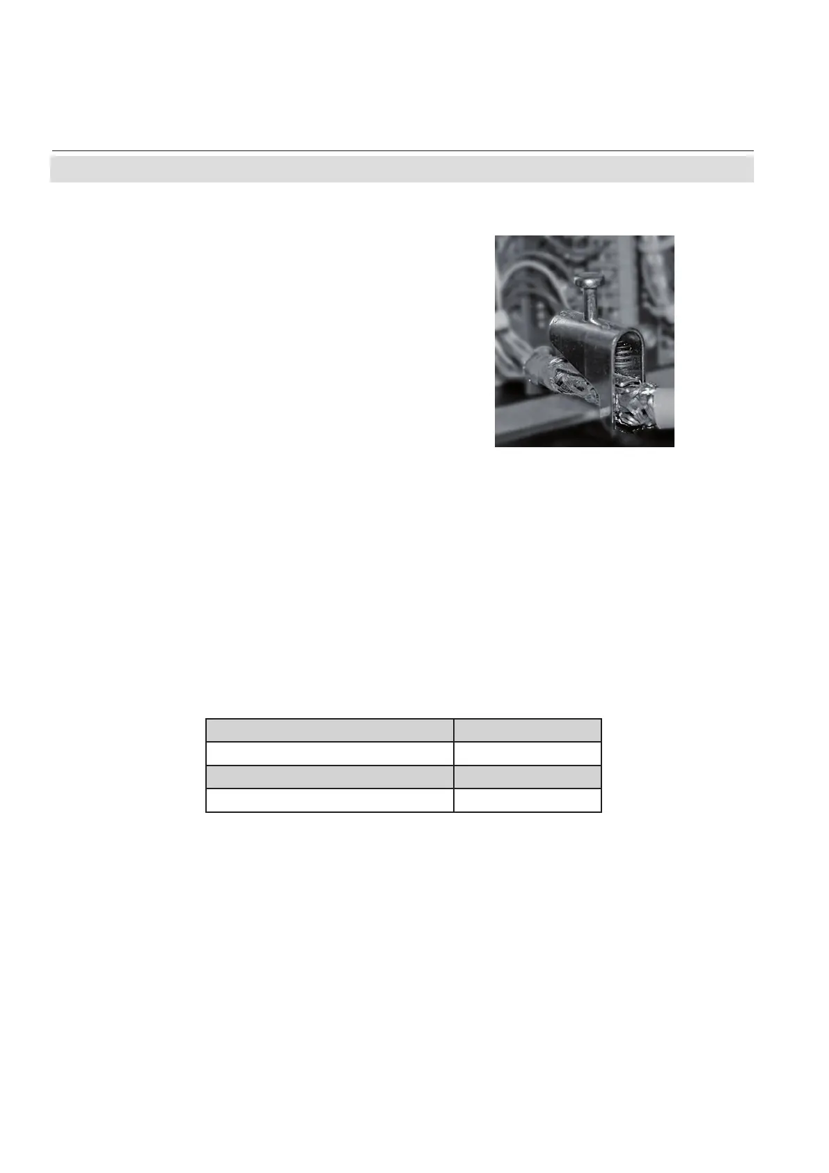
Fig. 4-27: Shield Connector Terminal With Cable
4.7 Installation - Notes on Wiring
The shield connector must be ordered to t the cable diameter, and can be retrotted:
Ø 1.5…6.5 mm (0.06"…0.25") part # ETC02019
Ø 5…11 mm (0.2"…0.43") part # ETC02020
Ø 10…17 mm (0.4"…0.66") part # ETC02021
Ø 16…24 mm (0.63"…0.94") part # ETC02022
X-STREAM XEGP with screw-type terminal
adapters
In order to avoid measured values being inu-
enced by external interference signals when
terminal adapters are in use, the signal cable
shieldings must be connected to the analy-
zer housing by means of shield connector
terminals:
• Strip the signal cable to a length of 20 cm
(8"). Take care to not damage the braided
shield!
• Pull up the contact part of the shield con-
nector terminal,
• feed through the cable as illustrated in
Fig. 4-27, and
• release the contact part down onto the
braided shield.
The result is a secure contact with the cable
shield, improving the unit’s immunity against
interference from other electronic devices.
Finally connect the individual wires as descri-
bed in section 4.6.1.