Emerson Process Management GmbH & Co. OHG 3-3
X-STREAM XE
Instruction Manual
HASXEE-IM-HS
10/2012
3
Measuring Principles
3.1.2 NDIR Detector
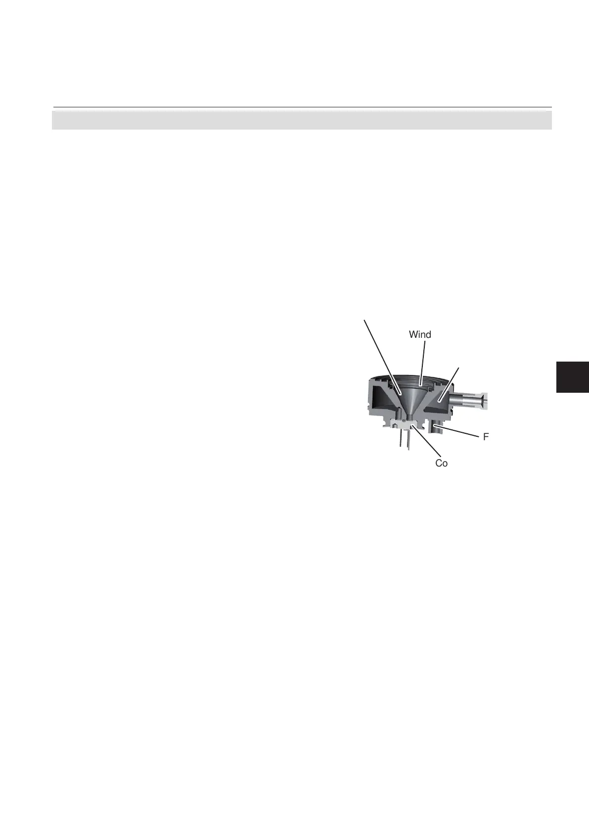
Fig. 3-2: Gas Detector Design Principle
Compensation chamber
Fill nozzle
Absorption chamber
Connecting channel
with
micro ow detector
Window
3.1 Infrared (IR) and Ultraviolet (UV) Measurement
The standard detector used for NDIR measure-
ments is an opto pneumatic detector. It con-
sists of two chambers, lled with gas and
connected via a small channel (Fig. 3-2).
The gas lling is chosen to provide maximum
overlap with the gas to be measured. Usually
the gas to be measured itself is used.
A micro ow sensor, placed in the connecting
channel, measures the ow between both
chambers. As light is absorbed by the gas in
the absorption chamber the gas temperature
changes resulting in an increase of volume of
the heated gas. The gas expands and ows
towards the compensation chamber. When
the chopper closes, no light is absorbed and
thus temperature and volume of the gas in the
absorption chamber decrease. Gas ows back
from the (now) hotter compensation chamber
into the absorption chamber. The absolute
ow, detected by the micro ow sensor, in
both cases is therefore a measure for the
light absorbed while the chopper is open. This
directly correlates to the amount of light not
absorbed in the analysis cell and therefore
to the concentration of the measurement gas
inside the analysis cell.
Using the divided analysis cell and the IntrinzX
chopper wheel enables simultaneous detection
of measurement and reference signal.