Emerson Process Management GmbH & Co. OHG4-26
X-STREAM XE
Instruction Manual
HASXEE-IM-HS
10/2012
4.6.2 Installation - X-STREAM XEXF Field Housings
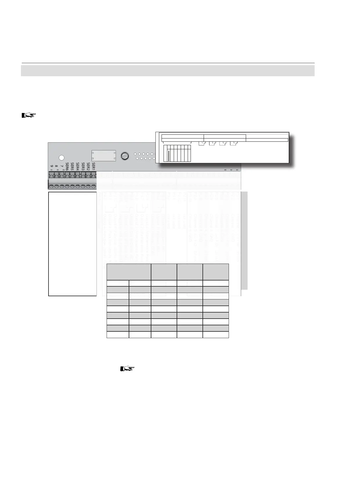
Serial interface
Specication and interface control:
Chapter 9
Fig. 4-19: Terminal Block X1 - Serial Interface
Notes!
Consider the installation notes in section
4.7 and the notes on installing cable glands
on page 4-22.
The 9 terminals on the left (28 - 36) of the right
most strip carry the serial interface signals.
X-STREAM analyzers are classified DTE
(Data Terminal Equipment).
Your analyzer´s type of serial interface is
marked on a label nearby the terminals (see
sample above)
Pin Signal
P2.1 Channel 1, (+) 4 (0) - 20 mA
P2.2 Channel 1, GND
P2.3 Channel 2, (+) 4 (0) - 20 mA
P2.4 Channel 2, GND
P2.5 Channel 3, (+) 4 (0) - 20 mA
P2.6 Channel 3, GND
P2.7 Channel 4, (+) 4 (0) - 20 mA
P2.8 Channel 4, GND
P2.9 Channel 5, (+) 4 (0) - 20 mA
P2.10 Channel 5, GND
P2.11 not used
P2.12 not used
P3.1 not used
P3.2 not used
P3.3 Output 1 (Failure), NC
P3.4 Output 1 (Failure), NO
P3.5 Output 1 (Failure), COM
P3.6 Output 2 (Maintenance Request), NC
P3.7 Output 2 (Maintenance Request), NO
P3.8 Output 2 (Maintenance Request), COM
P3.9 Output 3 (Out of Spec), NC
P3.10 Output 3 (Out of Spec), NO
P3.11 Output 3 (Out of Spec), COM
P3.12 Output 4 (Function check), NC
P4.1 Output 4 (Function check), NO
P4.2 Output 4 (Function check), COM
P4.3 not used
P4.4
P4.5
P4.6
P4.7
P4.8
P4.9
P4.10
P4.11
P4.12
Relay Outputs
**)
Analog Outputs
Serial Interface
*)
*)
See table
(Index:)
/4
Name
Datum
Verant.
Bearb.
(Zeichnung Nr.; Drawing No.)
(Benennung; Description)
EWo
EWo
4.271-8120
Bez.-Schild XSTA f. XPSA 02
Label XSTA f. XPSA 02
12.12.11
12.12.11
Index
Änderung
Datum
Name
1
0
0
m
m
30 mm
128,00 mm
Aufkleber aus 3M SC 3698 A,
Grund silberfarbig, Druck einfarbig schwarz
und Schutzlack
Schutzpapier gekerbt
geschnitten auf Format
12
11
10
9
8
7
6
5
4
3
2
1
P2
P3
P4
ANALOG OUT 4
ANALOG OUT 2
ANALOG OUT 3
ANALOG OUT 1
GROUND 3
GROUND 1
GROUND 2
GROUND 4
K4
K3
K2 K1
X2
RS 232
RS 485 2W
RS 485 4W
MODBUS
CAN
FF
9- IOIO -1
12
11
10
9
8
7
6
5
4
3
2
1
12
11
10
9
8
7
6
5
4
3
2
1
GROUND 5
ANALOG OUT 5
X
Terminal
MOD 485/
2 wire
MOD 485/
4 wire
RS 232
P4.4 SER1 Common Common Common
P4.5 SER2
not used not used
RXD
P4.6 SER3
not used not used
TXD
P4.7 SER4
not used
RXD1(+)
not used
P4.8 SER5 D1(+) TXD1(+) Common
P4.9 SER6
not used not used not used
P4.10 7
not used not used not used
P4.11 8
not used
RXD0(-)
not used
P4.12 9 D0(-) TXD0(-)
not used