Emerson Process Management GmbH & Co. OHG A-31
X-STREAM XE
Instruction Manual
HASXEE-IM-HS
10/2012
A
Appendix
Druck
Ch1
P31P30
Pressure
Ch2
Temperatur
Ch1
P18P17P16P11
Temperature
Ch4Ch3Ch2
Durchfluss
Ch1
P6P7P4P5
Flow
Ch4Ch3Ch2
AC-Detektoren
Ch1
P24P25P23P21
AC-detectors
Ch4Ch3Ch2 Ch5
Strahler
Ch1
P15P14P13P12
Source
Ch4Ch3Ch2
DC-Detektoren
Ch1
P20P19P26
ChopperDC-detectors
M2M1Ch4Ch2
P27
physikalische Baugruppen (messprinzipabhängig)
thermostatisiert (Option)
physical components (depending on measurement system)
Thermostate control (option)
siehe Blatt 3, 5, 8
see sheet 3, 5, 8
P32
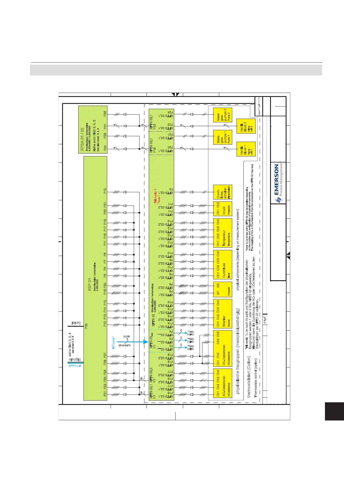
XSP 01, XPSA 02 and physical components in dual compartment fieldhousing
XFTB 02.1
P16
Stromlaufplan / schematics:
4
.350-0900
XFTB 02.1
P7
XFTB 02.1
P17
XFTB 02.2
P16
XFTB 02.2
P17
XFTB 02.1
P18
XFTB 02.2
P18
XFTB 02.1
P14
XFTB 02.2
P15
XFTB 02.1
P14
XFTB 02.2
P15
XFTB 02.1
P8
XFTB 02.2
P8
XFTB 02.1
P9
XFTB 02.1
P10
XFTB 02.2
P9
XFTB 02.2
P10
XFTB 02.1
P12
XFTB 02.1
P13
XFTB 02.2
P12
XFTB 02.2
P13
XFTB 02.1
P11
XFTB 02.1
P5
XFTB 02.2
P11
34
XFTB 02.2
P7
*Hinweis 1: Je nach Anzahl und Konfiguration der physikalischen
B
augruppen werden 1 oder 2 Stk. XFTB 02 eingesetzt.
Hierdurch kann die Zuordnung der AC- oder DC-Detektoren zu den
Steckplätzen der XFTB 02 variieren.
XFTB 02.1
P20
XFTB 02.1
P21
XFTB 02.1
P19
XSP 01
Stromlaufplan / schematics:
4.350-0520
8
XFTB 02.1
P23
XFTB 02.1
P24
XFTB 02.1
P22
34
9
8
9
*Hinweis 1
*Note 1
XFTB 02
2
+Power
4.300-9125
8/C10
XFTB 02....
P2
XFTB 02....
P3
XFTB 02....
P4
XFTB 02....
P1
2
13/E11
13/B...
2
13/E11
13/B...
2
13/E11
13/B...
*Note 1: Up to two pcb’s XFTB 02 may be installed depending
on the number and configuration of physical components.
The mapping of AC- or DC-Detectors from the connectors on the XFTB 02 may vary.
8
Ventil-
block 1
Valve-
unit 1
Ventil-
block 2
Valve-
unit 2
Mess
gas-
pumpe 1
Pump 1 Pump 2
P29
P21
P28
P24
8
8
8
Mess
gas-
pumpe 2
Durch-
fluss-
schalter
Flow-Switch
P10
XPSA 01 / 02
Stromlaufplan / schematics:
4.300-4660 / 4.350-0920
siehe auch Blatt 3, 5, 8
see also sheet 3, 5, 8
+Power
Signals
Serial
11
Weitergabe sowie Vervielfältigung dieser
Unterlage, Verwertung und Mitteilung ihres
Inhaltes sind nur mit unserer Zustimmung
gestattet. Alle Rechte vorbehalten.
Copying of this document, and giving it to
others and the use or communication of the
contents thereof, are only allowed with our
agreement. All rights are reserved.
E
Micro Index Änderung, revision Datum Name
Bearb.
Gepr.
20___
Datum Name
Beschreibung, description Zeichnung-Nr.: Drawing-No.: Index
Ident-Nr.:
Blatt
Sheet
von
of
Auftrags-Nr.:
+
=
D
C
B
A
E
D
C
B
A
1 2 3 4 5 6 7 8 9 10 11 12 13 14 15 16
1 2 3 4 5 6 7 8 9 10 11 12 13 14 15 16
4.300-5159/4
09
X-STREAM XE
Block diagram
15.04.
Bangert
Walther
15.04.
B
TN387: XPSA jetzt 5-kanalig
28.09.09 MBa
C MBa
TN847: Trace Moisture hinzu; TN489
11.11.10
D MBa
TN892: Aktualisiert
20.01.11
15
F
E MBa
TN1274: Aktualisiert
11.11.11
F
TN1346, TN1347: Aktualisiert
19.01.12
A.4 Block Diagram