104 Functional description CG Drives & Automation 01-7318-01r1
Digital Comparator 4 [6154]
Function is identical to digital comparator 1 [6151].
11.7.2 Logic Output Y [620]
By means of an expression editor, the comparator signals can
be logically combined into the Logic Y function.
The expression editor has the following features:
• The following signals can be used:
CA1, CA2, CD1, CD2 or LZ (or LY)
• The following signals can be inverted:
!A1, !A2, !D1, !D2, or !LZ (or !LY)
• The following logical operators are available:
"+" : OR operator
"&" : AND operator
"^" : EXOR operator
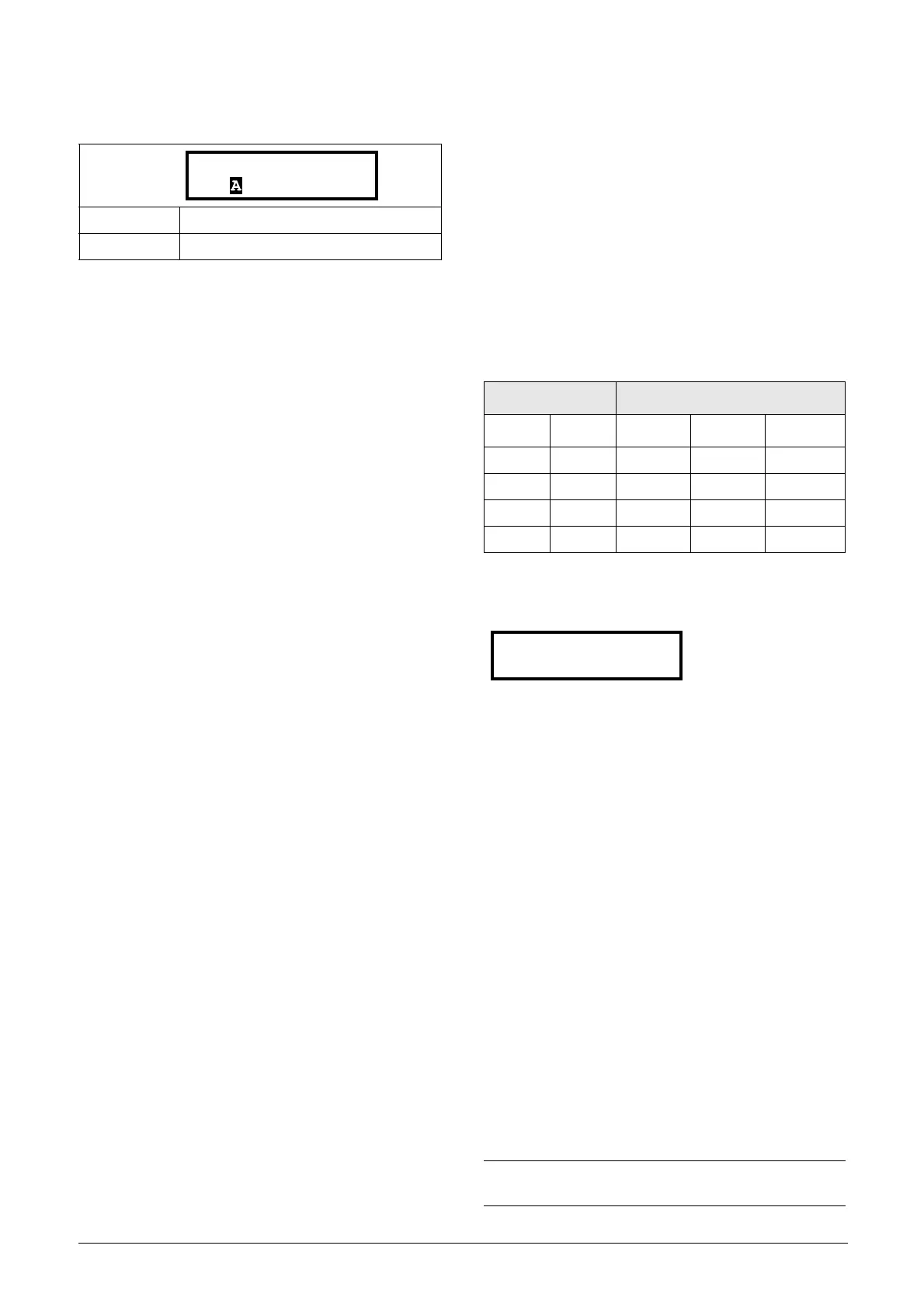
Expressions according to the following truth table can be
made:
The output signal can be programmed to the digital or relay
outputs or used as a Virtual Connection Source [560].
The expression must be programmed by means of the
menus [621] to [625].
Example:
Broken belt detection for Logic Y
This example describes the programming for a so-called
“broken belt detection” for fan applications.
The comparator CA1 is set for frequency>10Hz.
The comparator !A2 is set for load < 20%.
The comparator CD1 is set for Run.
The 3 comparators are all AND-ed, given the “broken belt
detection”.
In menus [621]-[625] expression entered for Logic Y is
visible.
Set menu [621] to CA1
Set menu [622] to &
Set menu [623] to !A2
Set menu [624] to &
Set menu [625] to CD1
Menu [620] now holds the expression for Logic Y:
CA1&!A2&CD1
which is to be read as:
(CA1&!A2)&CD1
Default: Ready
Selection: Same selections as for “DigOut 1 [541]”.
Input Result
A B & (AND) + (OR)
^(EXOR)
00000
01011
10011
11110
NOTE: Set menu [624] to "
." to finish the expression
when only two comparators are required for Logic Y.
620 LOGIC Y
Stp CA1&!A2&CD1

 Loading...