CG Drives & Automation 01-7318-01r1 Functional description 107
11.7.4 Timer1 [640]
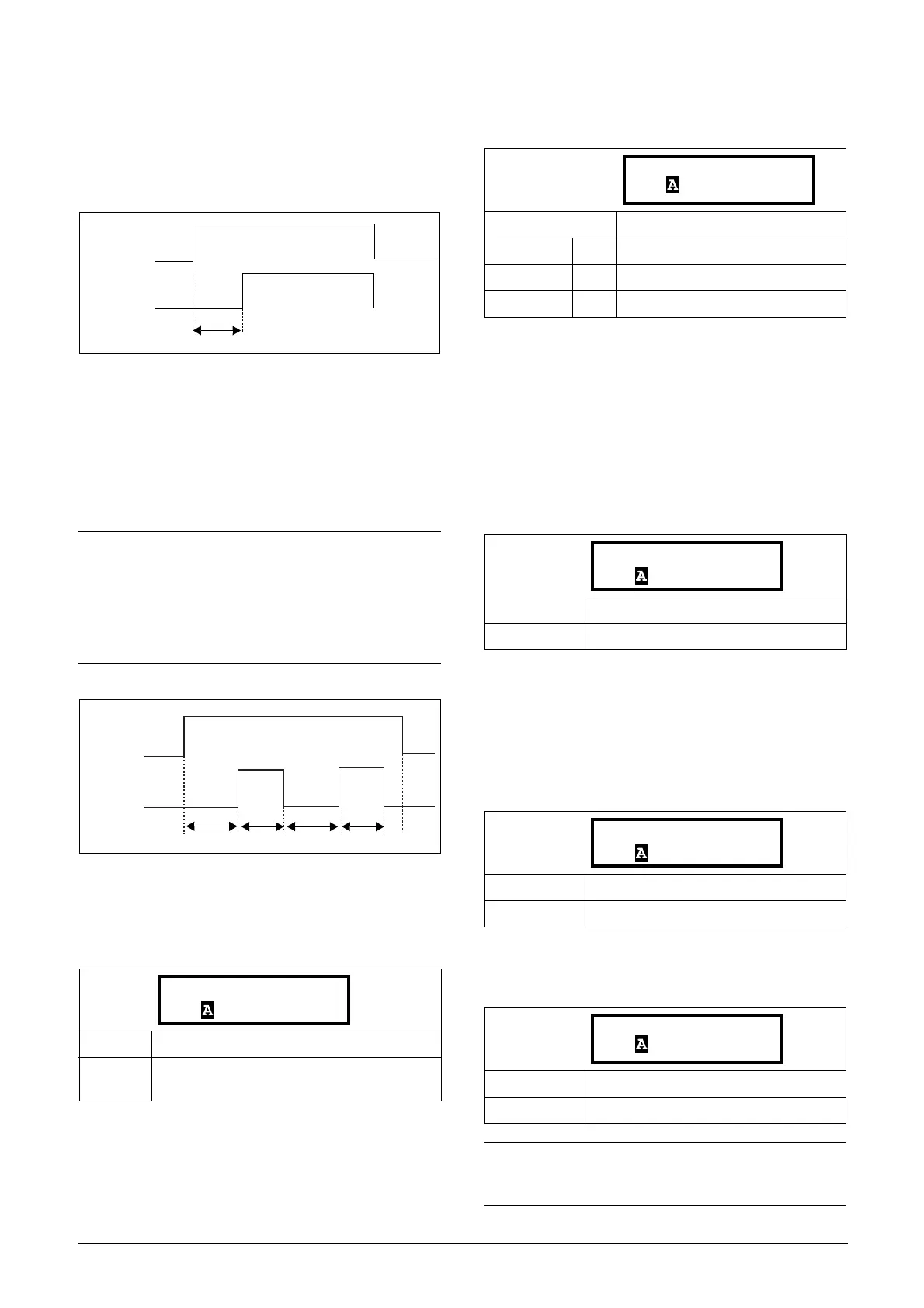
The Timer functions can be used as a delay timer or as an
interval with separate On and Off times (alternate mode). In
delay mode, the output signal T1Q becomes high if the set
delay time is expired. See Fig. 82.
Fig. 82
In alternate mode, the output signal T1Q will switch
automatically from high to low etc. according to the set
interval times “Timer1 T1” and “Timer 1 T2”. See Fig. 83.
The output signal can be programmed to the digital or relay
outputs used in logic functions [620] and [630], or as a
virtual connection source [560].
Fig. 83
Timer 1 Trig [641]
Selection of the Timer input trigger signal.
Timer 1 Mode [642]
Selection of mode of operation for Timer.
Timer 1 Delay [643]
This menu is only visible when timer mode is set to delay.
This menu can only be edited as in alternative 2, see section
9.7.
Timer 1 delay sets the time that will be used by the first
timer after it is activated. Timer 1 can be activated by a high
signal on a DigIn that is set to Timer 1 or via a virtual
destination [560].
Timer 1 T1 [644]
When timer mode is set to Alternate and Timer 1 is enabled,
this timer will automatically keep on switching according to
the independently programmable on and off times. The
Timer 1 in Alternate mode can be enabled by a digital input
or via a virtual connection. See Fig. 83. Timer 1 T1 sets the
on time in the alternate mode.
Timer 1 T2 [645]
Timer 1 T2 sets the off time in the alternate mode.
NOTE:
The actual timers are common for all parameter sets.
If the actual set is changed, the timer functionality
[641] to [645] will change according set settings but
the timer value will stay unchanged. So initialization
of the timer might differ for a set change compared to
normal triggering of a timer.
Default: Off
Selection:
Same selections as Digital Output 1 menu
[541].
Timer1 Trig
T1Q
Timer1 delay
Timer1 T2
Timer1 T1
Timer1 Trig
T1Q
Timer1 T2
Timer1 T1
Default: Off
Off 0
Delay 1
Alternate 2
Default: 00:00:00 (hr:min:sec)
Range: 00:00:00–9:59:59
Default: 00:00:00 (hr:min:sec)
Range: 00:00:00–9:59:59
Default: 00:00:00, hr:min:sec
Range: 00:00:00–9:59:59
NOTE:
“Timer 1 T1 [644]” and “Timer 1 T2 [645]” are only
visible when Timer Mode is set to Alternate.
643 Timer1Delay
Stp 00:00:00
644 Timer 1 T1
Stp 00:00:00
645 Timer1 T2
Stp 00:00:00

 Loading...