42 FDUL/VFXR/FDUG/VFXG/AFR/AFG Main features CG Drives & Automation, 01-7318-01r1
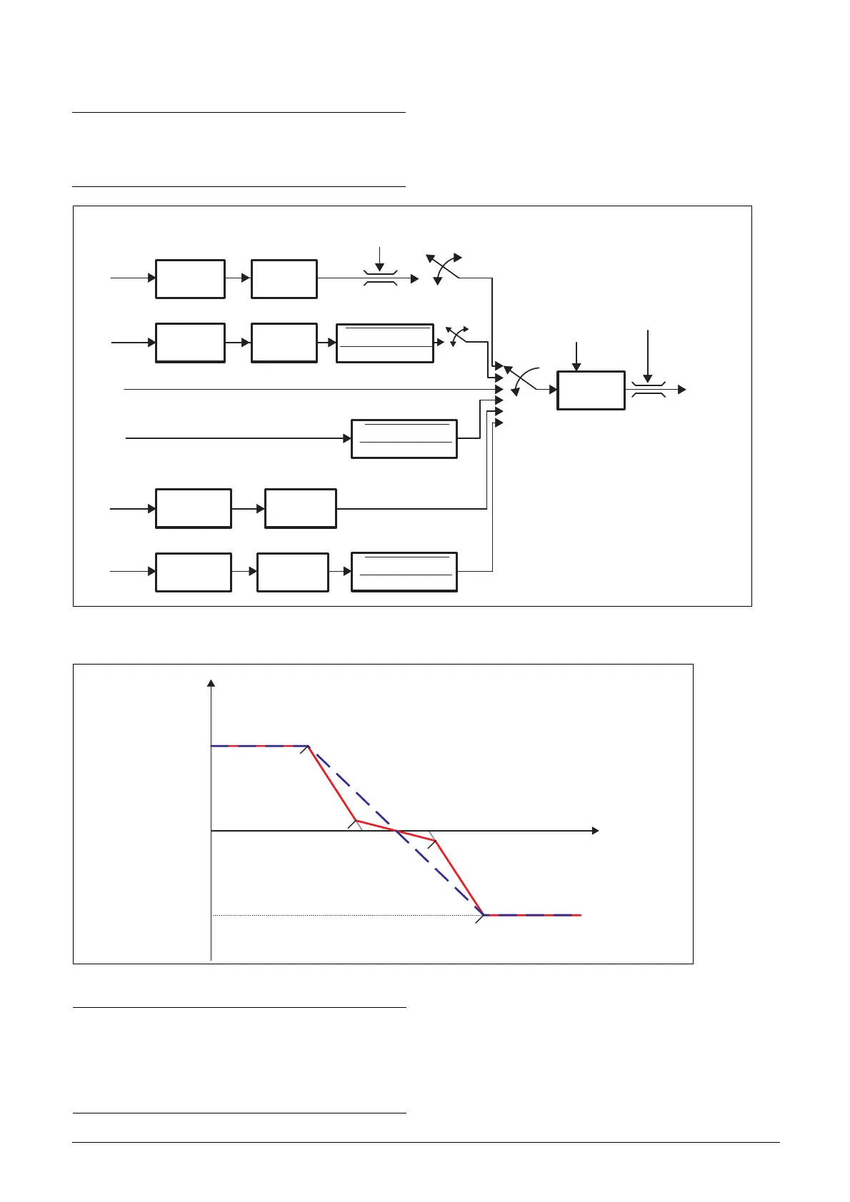
Fig. 37 Derivation of reactive power reference
Fig. 38 Typical Q-U and Cosθ-U characteristics curve
NOTE:
Q
ref
[310]
derived from reactive power (Q) support
functions ([G22] … [G27]) is further limited by maximum
reactive power limit (Q limit) defined in menu [O41].
Q
fix
[G22]
Cosθ
fix
[G23]
[G28]
P² . (1-cos²θ)
cosθ)
√
P² . (1-cos²θ)
cosθ)
√
P² . (1-cos²θ)
cosθ)
√
U
meas
U
meas
P
active
Limit check
P
active
Q
max
[041]
Q
ref
[031]
1st order
filter [G249]
1st order
filter [G259]
1st order
filter [G269]
1st order
filter [G279]
Q – U
curve [G24]
Cos
θ
– U
curve [G25]
curve [G27]
Cos
θ
– P
Q – P
curve [G26]
P lock-In [G24B]
P lock-Out [G24C]
Q-limit from [G24A]
(minimum Cos
θ)
P lock-In [G25B]
P
active
[G21]
P lock-Out [G25C]
(Q ,U )
11
(Q ,U )
22
(Q ,U )
33
(Q ,U )
44
Control Input
Control set point
(Q / Cos
θ
)
Max value
under excited
over excited
Max value
signal (U / P)
NOTE:
Actual reactive power capability of AFR/AFG is limited
by the ratings of the inverter. Therefore, the AFR/AFG
must be rated properly in order to have enough reactive
power available to fulfill the requirements laid by the
grid codes or grid operator.

 Loading...