CG Drives & Automation, 01-7318-01r1 FDUL/VFXR/FDUG/VFXG/AFR/AFG Main features 41
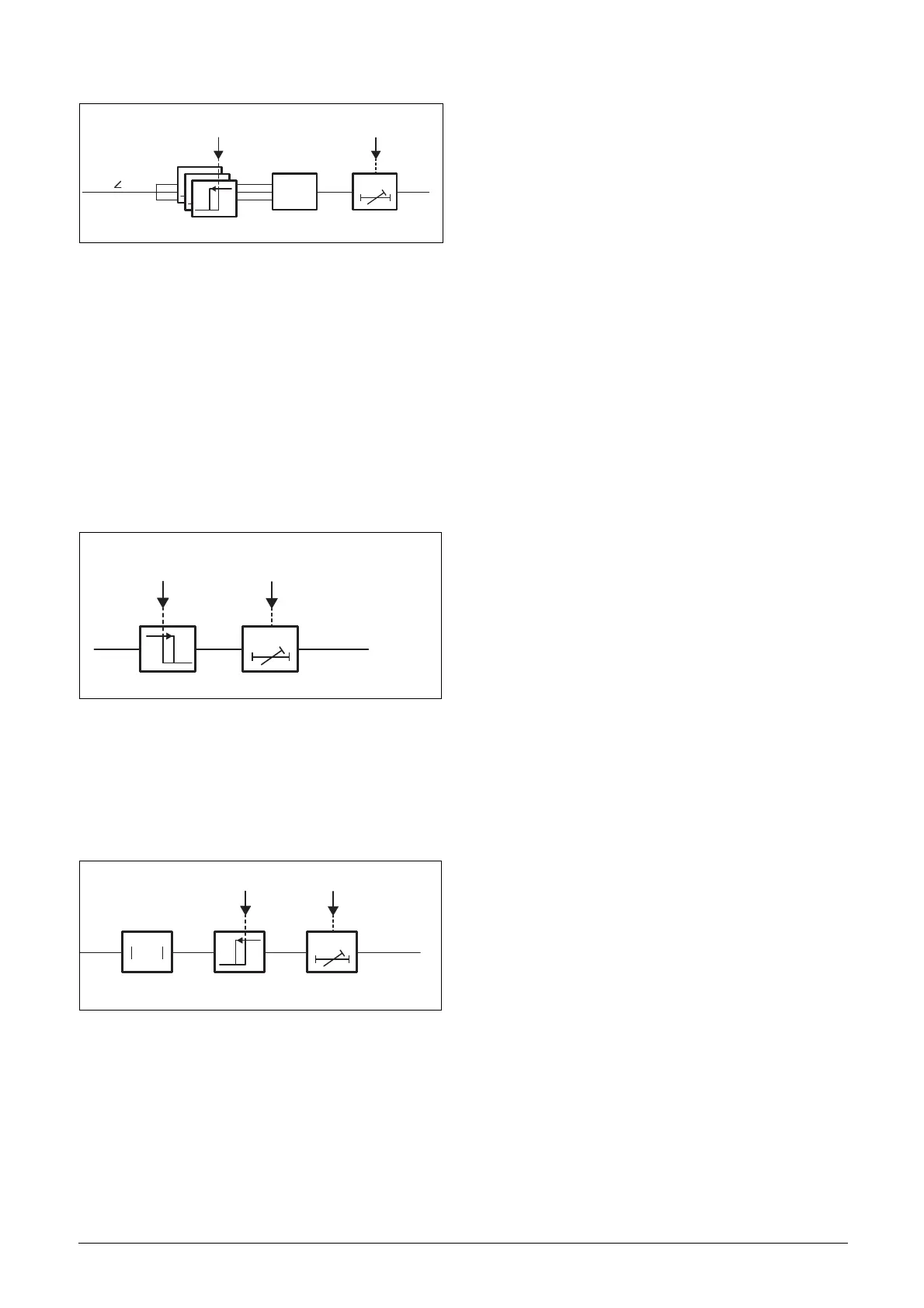
Fig. 34 Detailed block diagram of the three phase over-/under-
voltage protection (First over-voltage stage [3U>] is
shown).
The additional over- and under-voltage protection based on
the symmetrical voltages (U+, U- or U0) or the 10 minute
mean value (Umean(10min)) contains one stage with
independently settable trip levels and trip times. The
additional voltage protections are all of single type and uses
the same common hysteresis limit and reset timer as the
three phase voltage protection.
The over- and under-frequency protection contains two
stages (F>, F>> and F<, F<<), each with independently
settable trip levels and trip times, see Fig. 35. The frequency
protection contains one common hysteresis limit and reset
timer.
Fig. 35 Detailed block diagram of the over-/under-frequency
protection (Second under-frequency stage [F<<] is
shown).
The rate of change of frequency (ROCOF) protection
contains one stage (dF/dt<>), within settable trip level and
trip time, see Fig. 36. The ROCOF protection contains
hysteresis limit and reset timer.
Fig. 36 Detailed block diagram of ROCOF protection
functionality.
Voltage protection and frequency protection can be
configured in menus [G11] and [G12] respectively. Details
of these menus can be found in section 11.
7.17.2 Reactive power (Q) support
Often it is desired by the network operator that generating
plants connected to network operators network must be able
to provide voltage or reactive power support. For that,
generating plants should have the possibility of supplying or
consuming reactive power to/from the network. To fulfill
the reactive power support requirements, Emotron AFR/
AFG offers number of different operating modes i.e.
•Q fix
•Cosθ fix
•Q (U)
•Cosθ(U)
•Q (P)
•Cosθ (P)
Q fix
AFR/AFG controls reactive power output according to the
set point.
Cosθ fix
AFR/AFG controls Cosθ at the supply terminals of AFR/
AFG according to the set point.
Q (U)
AFR/AFG controls reactive power output as a function of
measured supply voltage. For voltage related control mode, a
characteristic (Q-U) curve can be configured using 4
configurable points (user parameters) which defines the
reactive power behavior as a function of voltage. Response of
Q(U) control matches the dynamics of first order filter.
Cosθ(U)
AFR/AFG controls Cosθ of the output as a function of
measured supply voltage. For voltage related control mode, a
characteristic (Cosθ -U) curve can be configured using 4
configurable points (user parameters) which defines the
Cosθ behavior as a function of voltage. Response of Cosθ
(U) control matches the dynamics of first order filter.
Q (P)
AFR/AFG controls reactive power output as a function of
supplied active power. For power related control mode, a
characteristic (Q-P) curve can be configured using 4
configurable points (user parameters) which defines the
reactive power behavior as a function of active power.
Response of Q(P) control matches the dynamics of first
order filter.
Cosθ (P)
AFR/AFG controls Cosθ of the output as a function of
supplied active power. For power related control mode, a
characteristic (Cosθ -P) curve can be configured using 4
configurable points (user parameters) which defines the
Cosθ behaviour of the output as a function of active power.
Response of Cosθ (P) control matches the dynamics of first
order filter.
Fig. 37 shows the derivation of reactive power reference
[310] in different operating modes. Only one mode can be
active at a time. Fig. 38 shows the typical Q - U or Cosθ - U
characteristics curve. Characteristics curve can be configured
by defining 4-points in Q-U (Cosθ-U) reference frame.
dF/dt
ABS
dF/dt
>
<
t(dF/dt )
>
<
>
<
(dF/dt )

 Loading...