CG Drives & Automation 01-7318-01r1 Functional description 89
11.6.2 Digital Inputs [520]
Submenu with all the settings for the digital inputs.
Digital Input 1 [521]
To select the function of the digital input.
On the standard control board there are eight digital inputs.
If the same function is programmed for more than one input
that function will be activated according to “OR” logic if
nothing else is stated.
Digital Input 2 [522] to Digital Input 8
[528]
Same function as “DigIn 1 [521]”. Default function for
DigIn 3 is Enable and for DigIn 8 is Reset. For DigIn 4 to 7
the default function is Off.
NOTE: Additional inputs will become available when
the I/O option boards are connected.
Default: RunL
Off 0 The input is not active.
Ext. Trip 3
Be aware that if there is nothing
connected to the input, the AC drive will
trip at “External trip” immediately.
NOTE: The External Trip is active low.
NOTE: Activated according to “AND”
logic.
Stop 4
Stop command according to the selected
Stop mode in menu [33B].
NOTE: The Stop command is active low.
NOTE: Activated according to “AND”
logic.
Enable 5
Enable command. General start condition
to run the AC drive. If made low during
running the output of the AC drive is cut
off immediately, causing the motor to
coast to zero speed.
NOTE: If none of the digital inputs are
programmed to “Enable”, the internal
enable signal is active.
NOTE: Activated according to “AND”
logic.
RunR 6
Run Right command (positive speed). The
output of the AC drive will be a
clockwise rotary field.
RunL 7
Run Left command (negative speed). The
output of the AC drive will be a
counter-clockwise rotary field.
Reset 9
Reset command. To reset a Trip condition
and to enable the Autoreset function.
MotPot Up 13
Increases the internal reference value
according to the set AccMotPot time
[333]. Has the same function as a “real”
motor potentiometer, see Table 122.
MotPot
Down
14
Decreases the internal reference value
according to the set DecMotPot time
[334]. See MotPot Up.
Timer 1 21
Timer 1 Delay [643] will be activated on
the rising edge of this signal.
Timer 2 22
Timer 2 Delay [653] will be activated on
the rising edge of this signal.
Ext Mot
Tem p
27
Be aware that if there is nothing
connected to the input, the AC drive will
trip at
“External Motor Temp” immediately.
NOTE: The External Motor Temp is active
low.
Loc/Rem 28
Activate local mode defined in [2171] and
[2172].
LC Level 30
Liquid cooling low level signal.
NOTE: The Liquid Cooling Level is active
low.
Sleep 32
Possible to enter sleep mode through
DigIn
NOTE:
DigIn1 [521] and DigIn2 [522] are read only menus.
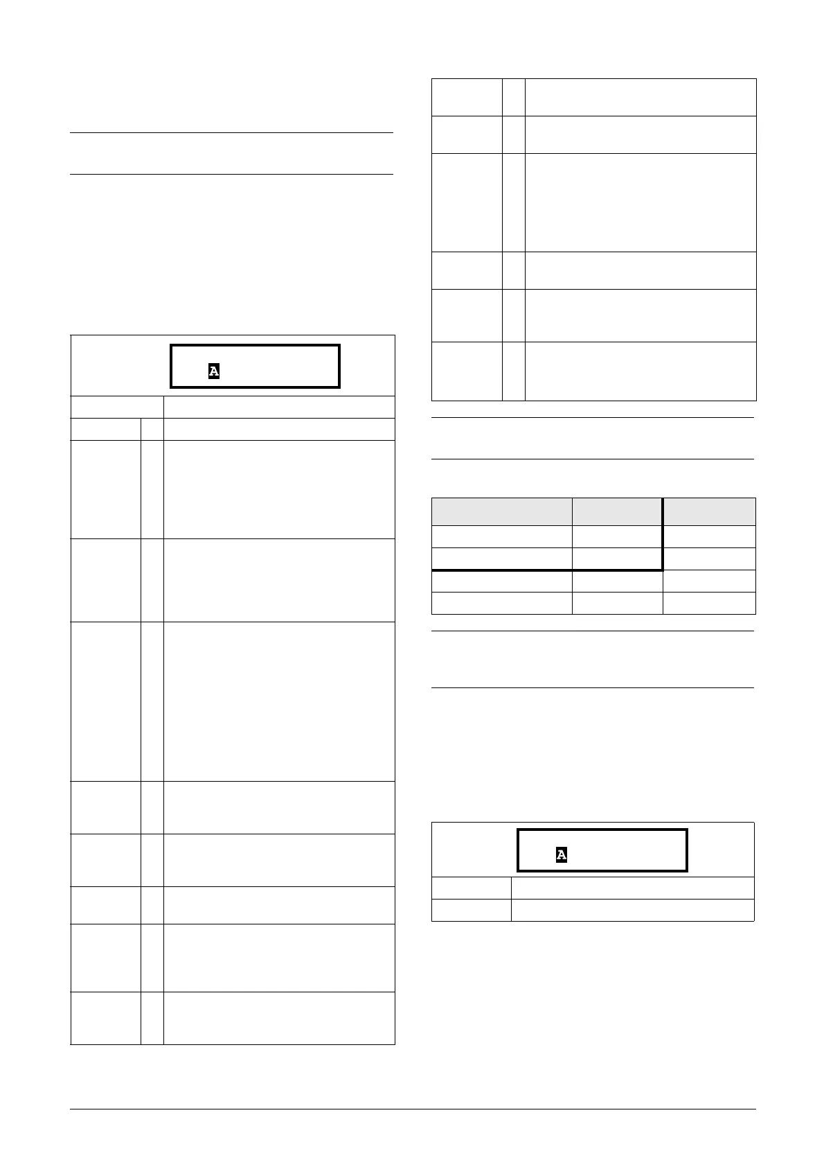
Ta b l e 2 2
Parameter Set Set Ctrl 1 Set Ctrl 2
A00
B10
C01
D11
NOTE:
To activate the parameter set selection, menu [241]
must be set to DigIn.
Default: RunR
Selection: Same as in menu
[521]

 Loading...