90 Functional description CG Drives & Automation 01-7318-01r1
Additional digital inputs [529] to
[52H]
Additional digital inputs with I/O option board installed,
“B1 DigIn 1 [529]” - “B3 DigIn 3 [52H]”. B stands for
board and 1 to 3 is the number of the board which is related
to the position of the I/O option board on the option
mounting plate. The functions and selections are the same as
“DigIn 1 [521]”. The default function is Off.
11.6.3 Analogue Outputs [530]
Submenu with all settings for the analogue outputs.
Selections can be made from application and AC drive
values, in order to visualize actual status. Analogue outputs
can also be used as a mirror of the analogue input. Such a
signal can be used as:
• a reference signal for the next AC drive in a Master/Slave
configuration (see Fig. 74).
• a feedback acknowledgement of the received analogue
reference value.
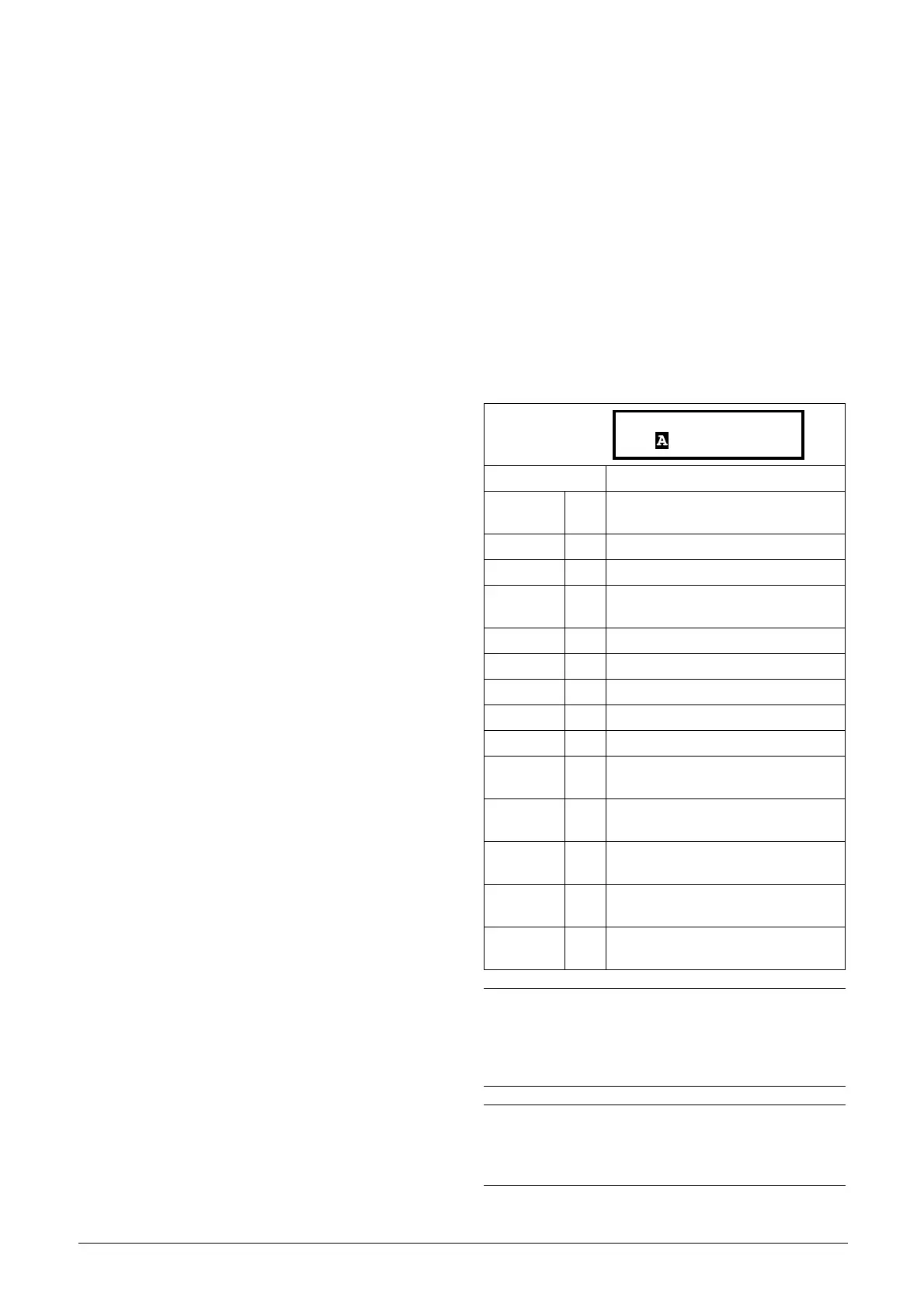
AnOut1 Function [531]
Sets the function for the Analogue Output 1. Scale and
range are defined by AnOut1 Advanced settings [533].
Default: Current
Process Val 0
Actual process value according to
Process feedback signal.
Torque 2 Actual torque.
Process Ref 3 Actual process reference value.
React
Power
4 Actual reactive power.
Frequency 5 Actual frequency.
Current 6 Actual current.
El power 7 Actual electrical power.
Output volt 8 Actual output voltage.
DC voltage 9 Actual DC link voltage.
AnIn1 10
Mirror of received signal value on
AnIn1.
AnIn2 11
Mirror of received signal value on
AnIn2.
AnIn3 12
Mirror of received signal value on
AnIn3.
AnIn4 13
Mirror of received signal value on
AnIn4.
Torq ue Re f 1 5
Actual torque reference value
(=0 in V/Hz mode)
NOTE:
When selections AnIn1, AnIn2 …. AnIn4 is selected,
the setup of the AnOut (menu [532] or [535]) has to be
set to 0-10V or 0-20mA. When the AnOut Setup is set
to e.g. 4-20mA, the mirroring is not working correct.
NOTE:
Output volt and DC voltage are presented as a
percentage of 1000 V (when selected on AnOut
function).

 Loading...