Emotron AB 01-3694-01r2 Functional Description 133
Z Comp 2 [633]
Selects the second comparator for the logic Z function.
Communication information
Z Operator 2 [634]
Selects the second operator for the logic Z function.
Communication information
Z Comp 3 [635]
Selects the third comparator for the logic Z function.
Communication information
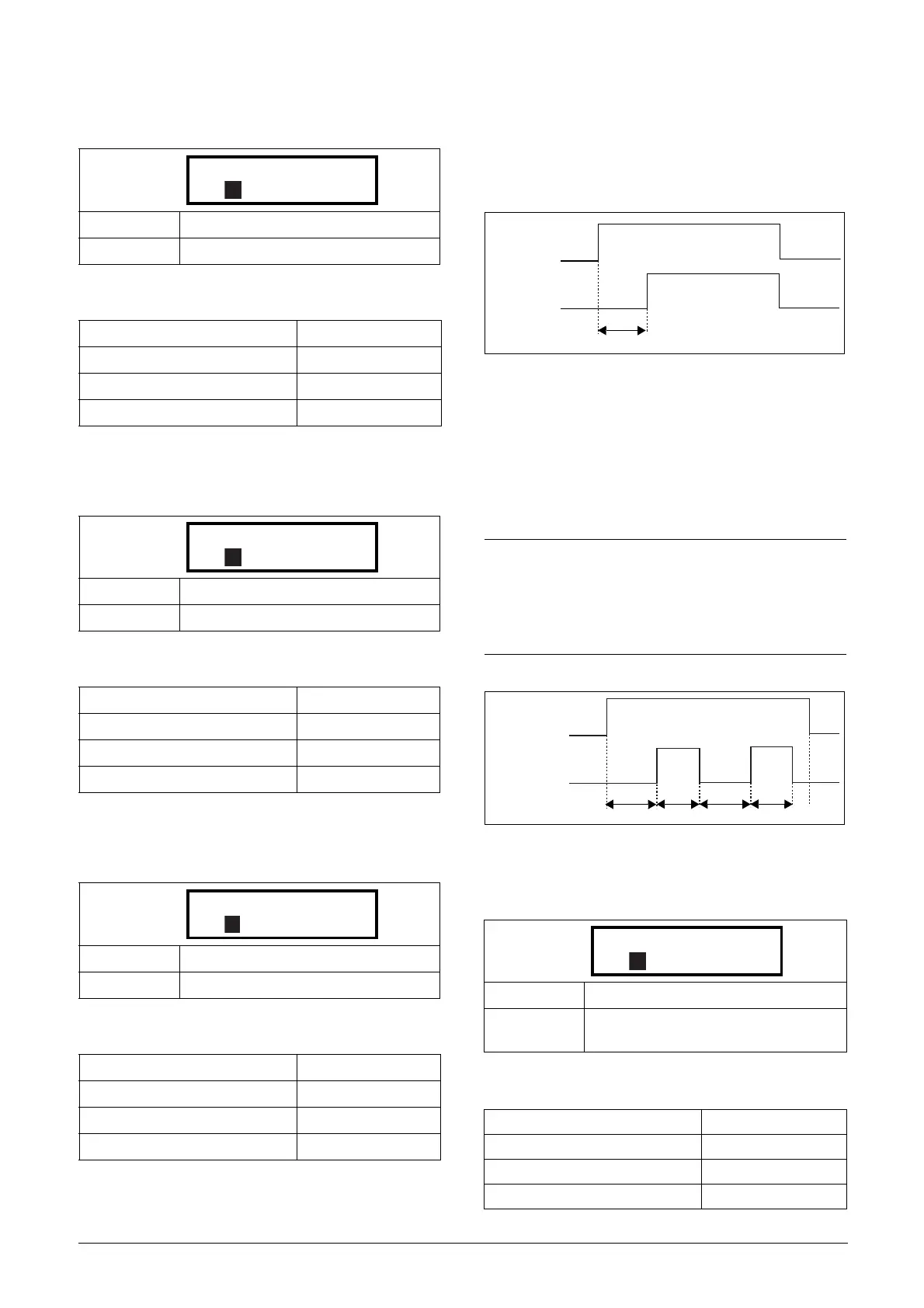
11.7.4 Timer1 [640]
The Timer functions can be used as a delay timer or as an
interval with separate On and Off times (alternate mode). In
delay mode, the output signal T1Q becomes high if the set
delay time is expired. See Fig. 108.
Fig. 108
In alternate mode, the output signal T1Q will switch auto-
matically from high to low etc. according to the set interval
times. See Fig. 109.
The output signal can be programmed to the digital or relay
outputs used in logic functions [620] and [630], or as a vir-
tual connection source [560].
Fig. 109
Timer 1 Trig [641]
Communication information
Default: !A2
Selection: Same as menu [621]
Modbus Instance no/DeviceNet no: 43423
Profibus slot/index 170/72
Fieldbus format UInt
Modbus format UInt
Default: &
Selection: Same as menu [624]
Modbus Instance no/DeviceNet no: 43424
Profibus slot/index 170/73
Fieldbus format UInt
Modbus format UInt
Default: CD1
Selection: Same as menu [621]
Modbus Instance no/DeviceNet no: 43425
Profibus slot/index 170/74
Fieldbus format UInt
Modbus format UInt
633 Z Comp 2
Stp !A2
A
634 Z Operator 2
Stp &
A
635 Z Comp 3
Stp CD1
A
NOTE: The actual timers are common for all parameter
sets. If the actual set is changed, the timer functionality
[641] to [645] will change according set settings but the
timer value will stay unchanged. So initialisation of the
timer might differ for a set change compared to normal
triggering of a timer.
Default: Off
Selection:
Same selections as Digital Output 1 menu
[541].
Modbus Instance no/DeviceNet no: 43431
Profibus slot/index 170/80
Fieldbus format UInt
Modbus format UInt
Timer1 Trig
or
DigInX=Timer1
T1Q
Timer1 delay
T1 T2 T1 T2
Timer1 Trig
or
DigIInX=Timer1
641 Timer1 Trig
Stp Off
A
 Loading...