Emotron AB 01-3694-01r2 Installation 19
Placing of motor cables
Keep the motor cables as far away from other cables as possi-
ble, especially from control signals. The minimum distance
between motor cables and control cables is 30 cm.
Avoid placing the motor cables in parallel with other cables.
The power cables should cross other cables at an angle of
90°.
Long motor cables
If the connection to the motor is longer than 100 m (40 m
for models 003-013), it is possible that capacitive current
peaks will cause tripping at overcurrent. Using output coils
can prevent this. Contact the supplier for appropriate coils.
Switching in motor cables
Switching in the motor connections is not advisable. In the
event that it cannot be avoided (e.g. emergency or mainte-
nance switches) only switch if the current is zero. If this is
not done, the VSD can trip as a result of current peaks.
3.2.2 Mains cables
Dimension the mains and motor cables according to local
regulations. The cable must be able to carry the VSD load
current.
Recommendations for selecting mains
cables
• To fulfil EMC purposes it is not necessary to use
screened mains cables.
• Use heat-resistant cables, +60°C or higher.
• Dimension the cables and fuses in accordance with local
regulations and the nominal output current of the
motor. See table 43, page 162.
• The litz connection is only necessary if the mounting
plate is painted. All the variable speed drives have an
unpainted back side and are therefore suitable for
mounting on an unpainted mounting plate.
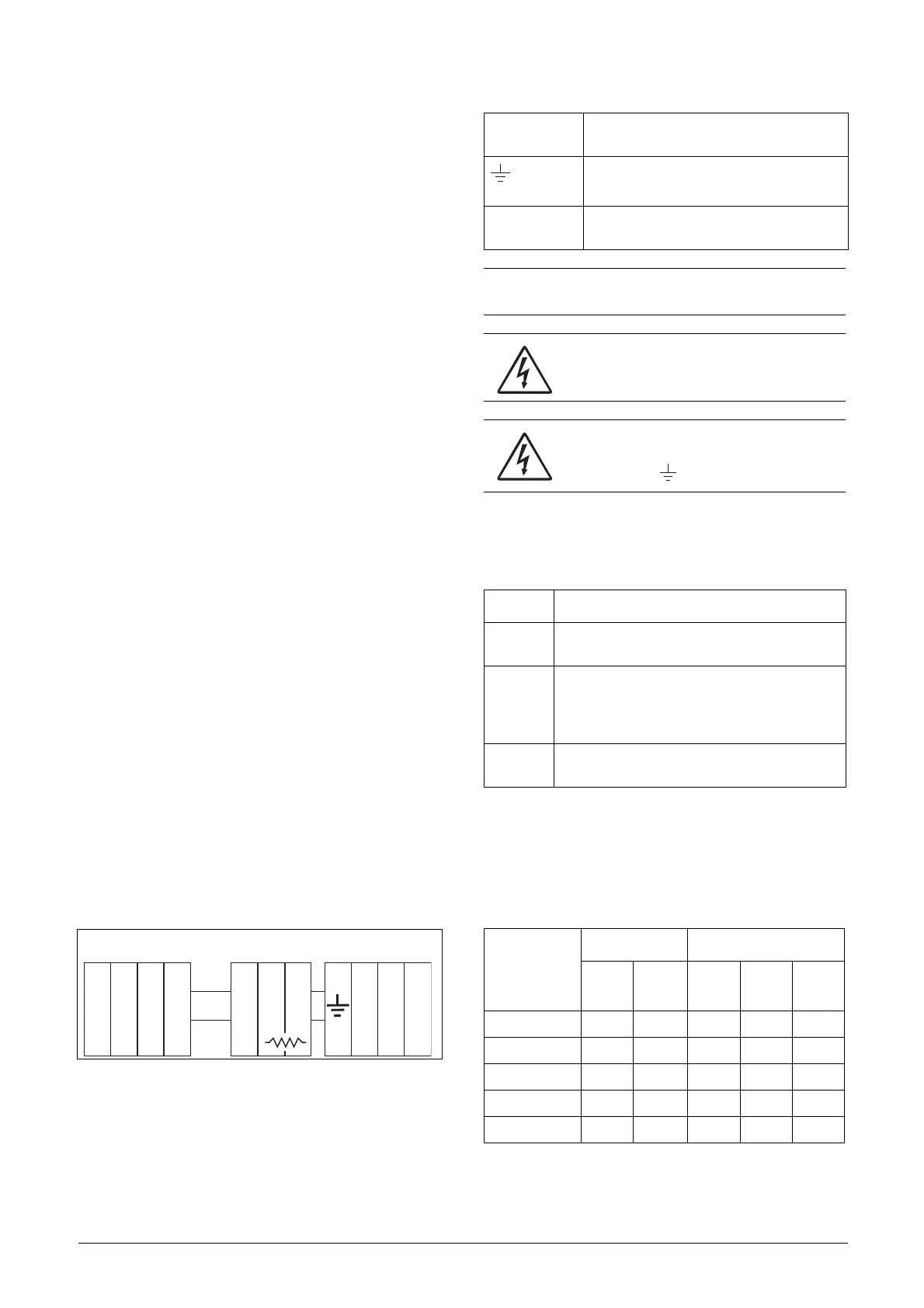
Connect the mains cables according to Fig. 23. The VSD
has a built-in RFI mains filter that complies with category
C3 which suits the Second Environment standard.
Fig. 23 Mains and motor connections
3.3 Cable specifications
3.4 Stripping lengths
Fig. 24 indicates the recommended stripping lengths for
motor and mains cables.
L2 L3 PEL1 U V WR
DC
+
DC
-
OPTION
Table 6 Mains and motor connection
L1,L2,L3
PE
Mains supply, 3 -phase
Safety earth (protected earth)
U, V, W
Motor earth
Motor output, 3-phase
(DC-),DC+,R
Brake resistor, DC-link
connections (optional)
NOTE: The Brake and DC-link Terminals are only fitted if
the Brake Chopper Option is built-in.
WARNING: The Brake Resistor must be
connected between terminals DC+ and R.
WARNING: In order to work safely, the mains
earth must be connected to PE and the
motor earth to .
Table 7 Cable specifications
Cable Cable specification
Mains
Power cable suitable for fixed installation for the
voltage used.
Motor
Symmetrical three conductor cable with concen-
tric protection (PE) wire or a four conductor cable
with compact low-impedance concentric shield
for the voltage used.
Control
Control cable with low-impedance shield,
screened.
Table 8 Stripping lengths for mains and motor cables
Model
Mains cable Motor cable
a
(mm)
b
(mm)
a
(mm)
b
(mm)
c
(mm)
003–013 60 8 60 8 31
018–037 115 12 115 12 32
046–073 130 11 130 11 34
090-175 160 16 160 16 41
210–250 170 24 170 24 46
 Loading...