Emotron AB 01-3694-01r2 Installation 17
3. Installation
The description of installation in this chapter complies with
the EMC standards and the Machine Directive.
Select cable type and screening according to the EMC
requirements valid for the environment where the VSD is
installed.
3.1 Before installation
Read the following checklist and think through your appli-
cation before installation.
• External or internal control.
• Long motor cables (>100m).
• Motors in parallel.
• Functions.
• Suitable VSD size in proportion to the motor/applica-
tion.
• Mount separately supplied option boards according to
the instructions in the appropriate option manual.
If the VSD is temporarily stored before being connected,
please check the technical data for environmental condi-
tions. If the VSD is moved from a cold storage room to the
room where it is to be installed, condensation can form on
it. Allow the VSD to become fully acclimatised and wait
until any visible condensation has evaporated before con-
necting the mains voltage.
3.2 Cable connections
3.2.1 Motor cables
To comply with the EMC emission standards the variable
speed drive is provided with a RFI mains filter. The motor
cables must also be screened and connected on both sides. In
this way a so-called “Faraday cage” is created around the
VSD, motor cables and motor. The RFI currents are now
fed back to their source (the IGBTs) so the system stays
within the emission levels.
Recommendations for selecting motor
cables
• Use screened cables according to specification in table 7.
Use symmetrical shielded cable; three phase conductors
and a concentric or otherwise symmetrically constructed
PE conductor, and a shield.
• When the conductivity of the cable shield is <50% of the
conductivity of the phase conductor, a separate PE con-
ductor is required.
• Use heat-resistant cables, +60°C or higher.
• Dimension the cables and fuses in accordance with the
nominal output current of the motor. See table 43, page
162.
• Keep the motor cable between VSD and motor as short
as possible.
• The screening must be connected with a large contact
surface of preferable 360× and always at both ends, to
the motor housing and the VSD housing. When painted
mounting plates are used, do not be afraid to scrape
away the paint to obtain as large contact surface as possi-
ble at all mounting points for items such as saddles and
the bare cable screening. Relying just on the connection
made by the screw thread is not sufficient.
• The litz connection is only necessary if the mounting
plate is painted. All the variable speed drives have an
unpainted back side and are therefore suitable for
mounting on an unpainted mounting plate.
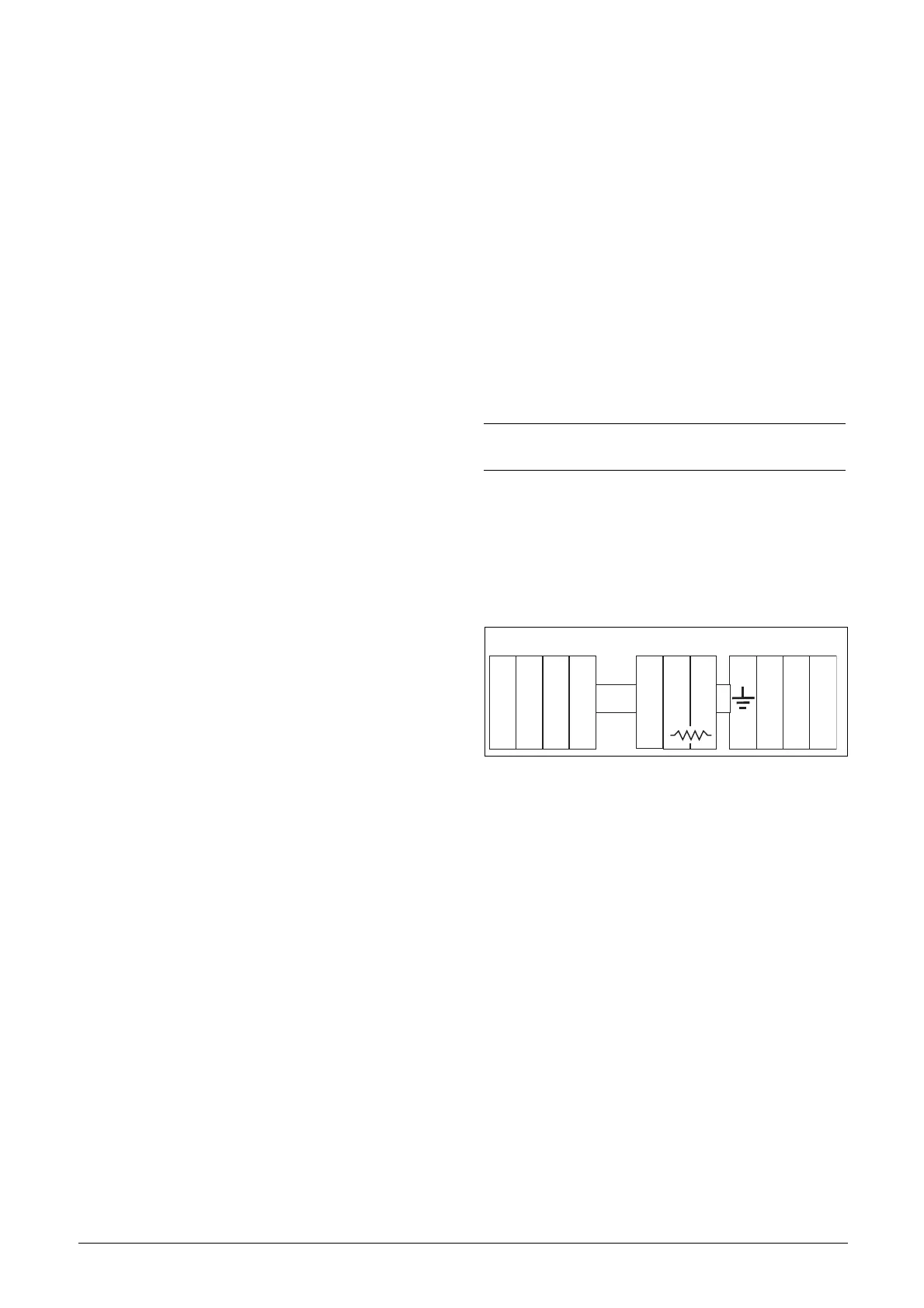
Connect the motor cables according to U - U, V - V and
W - W.
Fig. 19
Switches between the motor and the
VSD
If the motor cables are to be interrupted by maintenance
switches, output coils, etc., it is necessary that the screening
is continued by using metal housing, metal mounting plates,
etc. as shown in the Fig. 21.
Fig. 22 shows an example when there is no metal mounting
plate used (e.g. if IP54 variable speed drives are used). It is
important to keep the “circuit” closed, by using metal hous-
ing and cable glands.
NOTE: It is important that the motor housing has the
same earth potential as the other parts of the machine.
L2 L3 PEL1 U V WR
DC
+
DC
-
OPTION
 Loading...