Emotron AB 01-3694-01r2 Control Connections 23
4. Control Connections
4.1 Control board
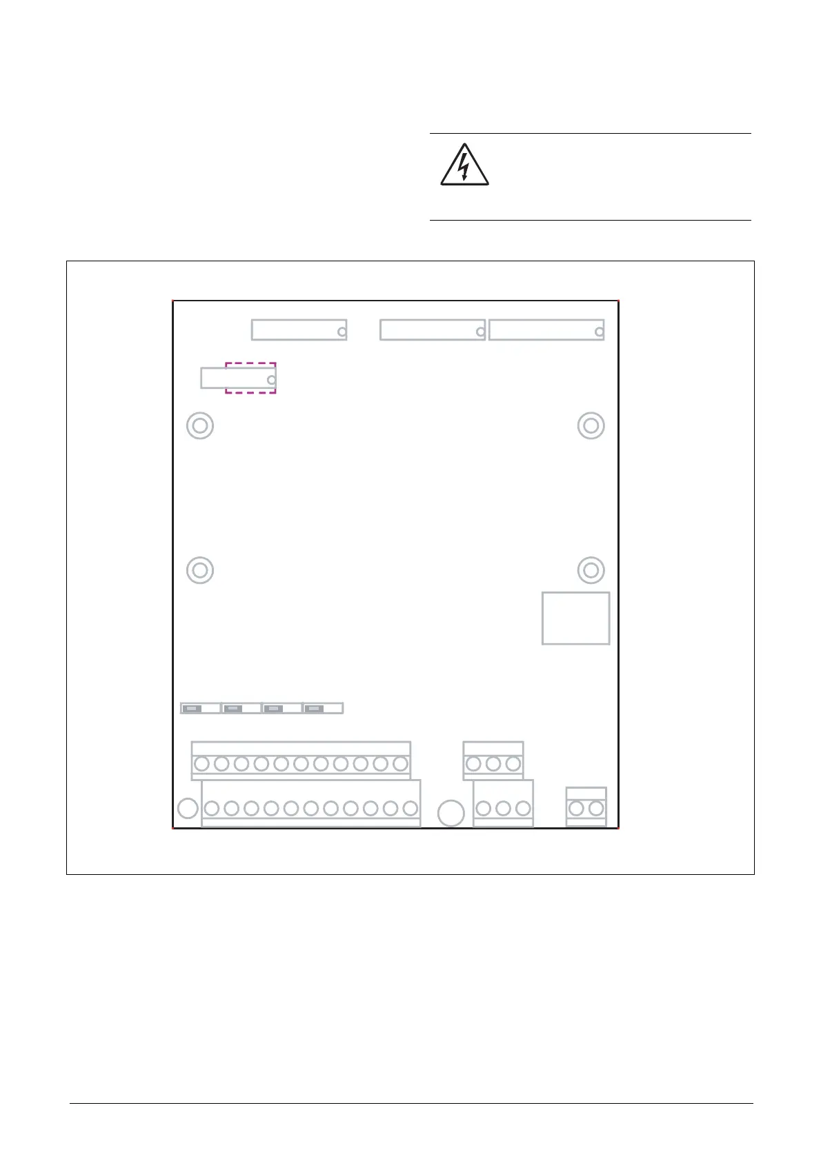
Fig. 27 shows the layout of the control board which is where
the parts most important to the user are located. Although
the control board is galvanically isolated from the mains, for
safety reasons do not make changes while the mains supply
is on!
Fig. 27 Control board layout
WARNING: Always switch off the mains
voltage and wait at least 5 minutes to allow
the buffer capacitors to discharge before
connecting the control signals or changing
position of the switches.
X8
X2
X3
X1
S2S1
S3 S4
X5
X4
X6
X7
U
II
UU
I
I
U
1
12
22
11
41
42 43
31 32
33
51
52
Relay outputs
Control
signals
Switches
Option
Control
Panel
Communication
 Loading...