48 Main Features Emotron AB 01-3694-01r2
7.6.9 Functional Examples of Start/
Stop Transitions
Starting an additional pump
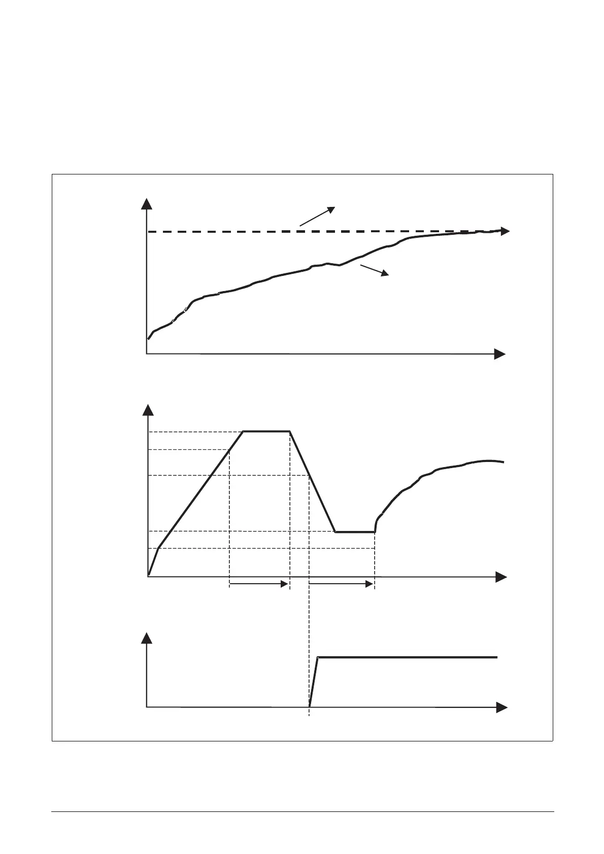
This figure shows a possible sequence with all levels and
functions involved when a additional pump is started by
means of the pump control relays. The starting of the sec-
ond pump is controlled by one of the relay outputs. The
relay in this example starts the pump directly on line. Of
course other start/stop equipment like a soft starter could be
controlled by the relay output.
Fig. 52 Time sequence starting an additional pump
Flow
Set view ref. [310]
Feedback Flow
time
Master pump
Max speed
Speed
Transition Speed Start
Min speed
Lower band
Upper band
Start delay [399] Settle time start [39D]
Start ramp depends
on start method
Start command
Speed
2nd pump
time
time
[39E]
[343]
[341]
 Loading...