Emotron AB 01-3694-01r2 Getting Started 29
5. Getting Started
This chapter is a step by step guide that will show you the
quickest way to get the motor shaft turning. We will show
you two examples, remote control and manual control.
We assume that the VSD is mounted on a wall or in a cabi-
net as in the chapter 2. page 9.
First there is general information of how to connect mains,
motor and control cables. The next section describes how to
use the function keys on the control panel. The subsequent
examples covering remote control and manual control
describe how to program/set the motor data and run the
VSD and motor.
5.1 Connect the mains and
motor cables
Dimension the mains and motor cables according to local
regulations. The cable must be able to carry the VSD load
current.
5.1.1 Mains cables
1. Connect the mains cables as in Fig. 31. The VSD has a
built-in RFI mains filter that complies with category C3
which suits the Second Environment standard.
5.1.2 Motor cables
2. Connect the motor cables as in Fig. 31. To comply with
the EMC Directive you have to use screened cables and
the motor cable screen has to be connected on both
sides: to the housing of the motor and the housing of the
VSD.
Fig. 31 Connection of mains and motor cables
WARNING: In order to work safely the mains
earth must be connected to PE and the motor
earth to .
5.2 Connect control cables
Here you will make up the minimum wiring for starting. In
this example the motor/VSD will run with right rotation.
To comply with the EMC standard, use screened control
cables with plaited flexible wire up to 1.5 mm
2
or solid wire
up to 2.5 mm
2
.
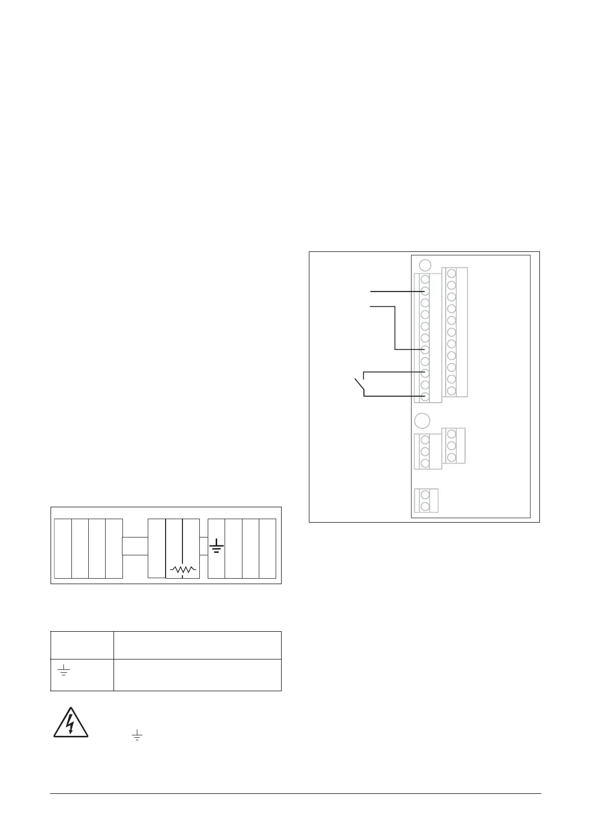
3. Connect a reference value between terminals 7 (Com-
mon) and 2 (AnIn 1) as in Fig. 32.
4. Connect an external start button between terminal 11
(+24 VDC) and 9 (DigIn1, RUNR) as inFig. 32.
Fig. 32 Wiring
Table 15 Mains and motor connection
L1,L2,L3
PE
Mains supply, 3 -phase
Safety earth
U, V, W
Motor earth
Motor output, 3-phase
L2 L3 PEL1 U V WR
DC
+
DC
-
X2
X3
X1
1
12
22
11
41
42
43
31
32
33
51
52
2
3
4
5
6
7
8
9
10
13
14
15
16
17
18
19
20
21
Start (RunR)
Reference
0-10 V
 Loading...