40 Main Features Emotron AB 01-3694-01r2
7.4 Using the Control Panel
Memory
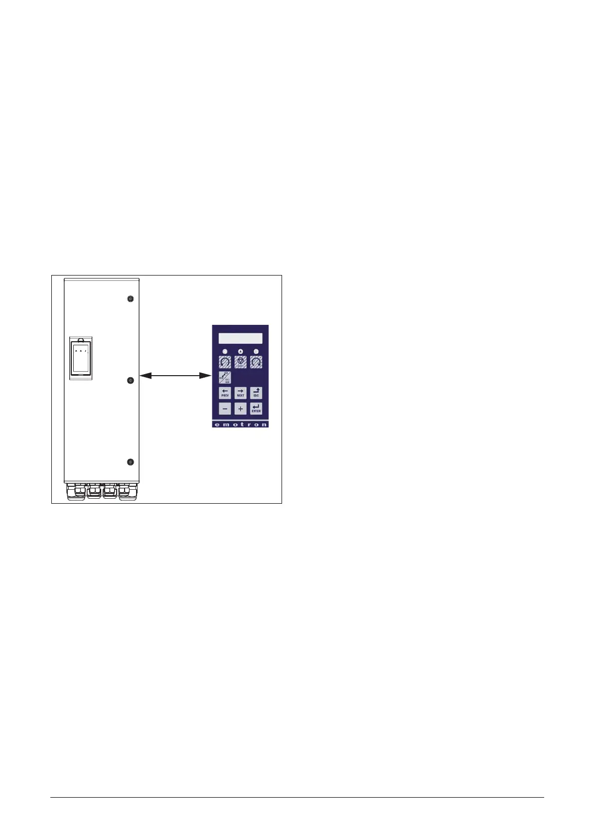
Data can be copied from the VSD to the memory in the
control panel and vice versa. To copy all data from the VSD
to the control panel, select Copy to CP[244], Copy to CP.
To copy data from the control panel to the VSD, enter the
menu [245], Load from CP and select what you want to
copy.
The memory in the control panel is useful in applications
with VSDs without a control panel and in applications
where several variable speed drives have the same setup. It
can also be used for temporary storage of settings. Use a con-
trol panel to upload the settings from one VSD and then
move the control panel to another VSD and download the
settings.
Fig. 40 Copy and load parameters between VSD and control
panel
7.5 Load Monitor and Process
Protection [400]
7.5.1 Load Monitor [410]
The monitor functions enable the VSD to be used as a load
monitor. Load monitors are used to protect machines and
processes against mechanical overload and underload, such
as a conveyer belt or screw conveyer jamming, belt failure on
a fan or a pump dry running. The load is measured in the
VSD by the calculated motor shaft torque. There is an over-
load alarm (Max Alarm and Max Pre-Alarm) and an under-
load alarm (Min Alarm and Min Pre-Alarm).
The Basic Monitor type uses fixed levels for overload and
underload (pre-)alarms over the whole speed range. This
function can be used in constant load applications where the
torque is not dependent on the speed, e.g. conveyor belt,
displacement pump, screw pump, etc.
For applications with a torque that is dependent on the
speed, the Load Curve monitor type is preferred. By measur-
ing the actual load curve of the process, characteristically
over the range of minimum speed to maximum speed, an
accurate protection at any speed can be established.
The max and min alarm can be set for a trip condition. The
pre-alarms act as a warning condition. All the alarms can be
monitored on the digital or relay outputs.
The autoset function automatically determines the 4 alarm
levels whilst running: maximum alarm, maximum pre-
alarm, minimum alarm and minimum pre-alarm.
Fig. 41 gives an example of the monitor functions for con-
stant torque applications.
VSD
 Loading...