Emotron AB 01-3694-01r2 Options 153
The brake chopper option is built-in by the manufacturer
and must be specified when the VSD is ordered.
13.5 I/O Board
The I/O option board 2.0 provides three extra relay outputs
and three extra digital inputs. The I/O Board works in com-
bination with the Pump/Fan Control, but can also be used
as a separate option. This option is described in a separate
manual.
13.6 Output coils
Output coils, which are supplied separately, are recom-
mended for lengths of screened motor cable longer than 40
m for FDU 40-003 to 013 and longer than 100 m for all
other VSD models. Because of the fast switching of the
motor voltage and the capacity of the motor cable both line
to line and line to earth screen, large switching currents can
be generated with long lengths of motor cable. Output coils
prevent the VSD from tripping and should be installed as
closely as possible to the VSD.
13.7 Serial communication and
fieldbus
For communication with the VSD there are several option
boards for communication. There are different options for
Fieldbus communication and one serial communication
option with RS232 or RS485 interface which has galvanic
isolation.
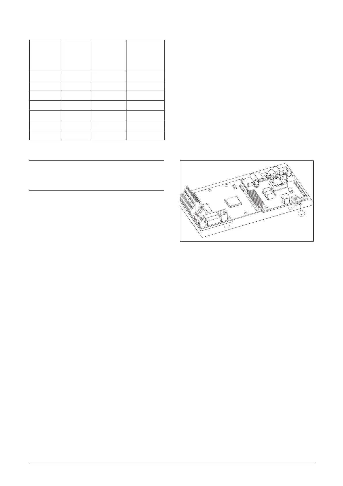
13.8 Standby supply option
The standby supply option provides the possibility of keep-
ing the communication system up and running without hav-
ing the 3-phase mains connected. One advantage is that the
system can be set up without mains power. The option will
also give backup for communication failure if main power is
lost.
The standby supply option is supplied with external
±10% 24 VDC or 24 VAC from a double isolated trans-
former.
Fig. 120 Connection of standby supply option
13.9 Safe Stop option
To realize a Safe Stop configuration in accordance with
EN954-1 Category 3, the following three parts need to be
attended to:
1. Inhibit trigger signals with safety relay K1 (via Safe Stop
option board).
2. Enable input and control of VSD (via normal I/O con-
trol signals of VSD).
3. Power conductor stage (checking status and feedback of
driver circuits and IGBT’s).
To enable the VSD to operate and run the motor, the fol-
lowing signals should be active:
• "Inhibit" input, terminals 1 (DC+) and 2 (DC-) on the
Safe Stop option board should be made active by con-
necting 24 VDC to secure the supply voltage for the
driver circuits of the power conductors via safety relay
K1. See also Fig. 122.
• High signal on the digital input, e.g. terminal 9 in Fig.
122, which is set to "Enable". For setting the digital
input please refer to section 11.6.2, page 118.
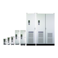
Table 32 Brake resistors 500 V types
Type
Max.supply
voltage AC
Brake level
VDC
Minimum
brake
resistance
Rmin [ohm]
FDU50-018 525 875 27
-026 525 875 27
-031 525 875 27
-037 525 875 27
-046 525 875 25
-060 525 875 12
-073 525 875 9.9
NOTE: Although the VSD will detect a failure in the brake
electronics, the use of resistors with a thermal overload
which will cut off the power at overload is strongly
recommended.
~
Must be
double
isolated
 Loading...