Emotron AB 01-3694-01r2 Control Connections 27
4.5.2 Types of control signals
Always make a distinction between the different types of sig-
nals. Because the different types of signals can adversely
affect each other, use a separate cable for each type. This is
often more practical because, for example, the cable from a
pressure sensor may be connected directly to the variable
speed drive.
We can distinguish between the following types of control
signals:
Analogue inputs
Voltage or current signals, (0-10 V, 0/4-20 mA) normally
used as control signals for speed, torque and PID feedback
signals.
Analogue outputs
Voltage or current signals, (0-10 V, 0/4-20 mA) which
change slowly or only occasionally in value. In general, these
are control or measurement signals.
Digital
Voltage or current signals (0-10 V, 0-24 V, 0/4-20 mA)
which can have only two values (high or low) and only occa-
sionally change in value.
Data
Usually voltage signals (0-5 V, 0-10 V) which change rapidly
and at a high frequency, generally data signals such as
RS232, RS485, Profibus, etc.
Relay
Relay contacts (0-250 VAC) can switch highly inductive
loads (auxiliary relay, lamp, valve, brake, etc.).
Example:
The relay output from a variable speed drive which controls
an auxiliary relay can, at the moment of switching, form a
source of interference (emission) for a measurement signal
from, for example, a pressure sensor. Therefore it is advised
to separate wiring and screening to reduce disturbances.
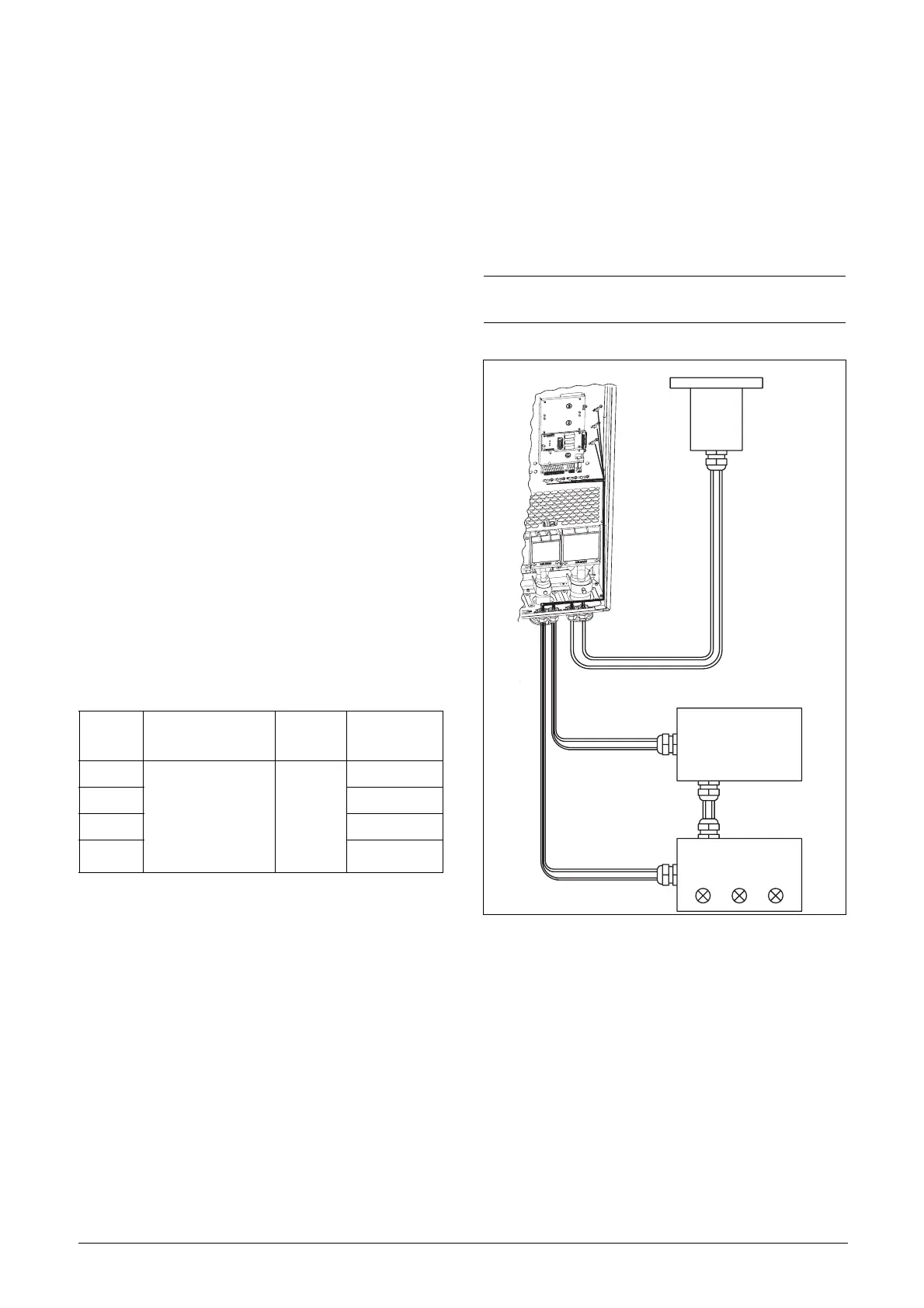
4.5.3 Screening
For all signal cables the best results are obtained if the
screening is connected to both ends: the VSD side and the at
the source (e.g. PLC, or computer). See Fig. 30.
It is strongly recommended that the signal cables be allowed
to cross mains and motor cables at a 90° angle. Do not let
the signal cable go in parallel with the mains and motor
cable.
4.5.4 Single-ended or double-ended
connection?
In principle, the same measures applied to motot cables
must be applied to all control signal cables, in accordance
with the EMC-Directives.
For all signal cables as mentioned in section 4.5.2 the best
results are obtained if the screening is connected to both
ends. See Fig. 30.
Fig. 30 Electro Magnetic (EM) screening of control signal
cables.
Signal
type
Maximum wire size
Tightening
torque
Cable type
Analogue Rigid cable:
0.14-2.5 mm
2
Flexible cable:
0.14-1.5 mm
2
Cable with ferrule:
0.25-1.5 mm
2
0.5 Nm
Screened
Digital Screened
Data Screened
Relay Not screened
NOTE: Each installation must be examined carefully
before applying the proper EMC measurements.
Control board
Pressure
sensor
(example)
External control
(e.g. in metal housing)
Control consol
 Loading...