26 Control Connections Emotron AB 01-3694-01r2
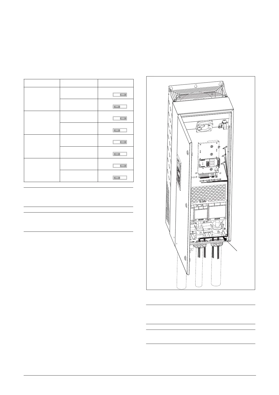
4.4 Inputs configuration
with the switches
The switches S1 to S4 are used to set the input configuration
for the 4 analogue inputs AnIn1, AnIn2, AnIn3 and AnIn4
as described in table 14. See Fig. 27 for the location of the
switches.
4.5 Connecting the Control
Signals
4.5.1 Cables
The standard control signal connections are suitable for
stranded flexible wire up to 1.5 mm
2
and for solid wire up to
2.5 mm
2
.
Fig. 29 Connecting the control signals
Table 14 Switch settings
Input Signal type Switch
AnIn1
Voltage
S1
Current (default)
S1
AnIn2
Voltage
S2
Current (default)
S2
AnIn3
Voltage
S3
Current (default)
S3
AnIn4
Voltage
S4
Current (default)
S4
NOTE: Scaling and offset of AnIn1 - AnIn4 can be
configured using the software. See menus [512], [515],
[518] and [51B] in section 11.6, page 112.
NOTE: the 2 analogue outputs AnOut 1 and AnOut 2 can
be configured via the software. See menu [530]
section 11.6.3, page 119
U
I
U
I
U
I
U
I
U
I
U
I
U
I
U
I
NOTE: The screening of control signal cables is
necessary to comply with the immunity levels given in
the EMC Directive (it reduces the noise level).
NOTE: Control cables must be separated from motor and
mains cables.
Control signals
 Loading...