18 Installation Emotron AB 01-3694-01r2
Fig. 20 Screening of cables for models 018 - 037.
Pay special attention to the following points:
• If paint must be removed, steps must be taken to prevent
subsequent corrosion. Repaint after making connections!
• The fastening of the whole variable speed drive housing
must be electrically connected with the mounting plate
over an area which is as large as possible. For this purpose
the removal of paint is necessary. An alternative method
is to connect the variable speed drive housing to the
mounting plate with as short a length of litz wire as pos-
sible.
• Try to avoid interruptions in the screening wherever pos-
sible.
• If the variable speed drive is mounted in a standard cabi-
net, the internal wiring must comply with the EMC
standard. Fig. 21 shows an example of a VSD built into a
cabinet.
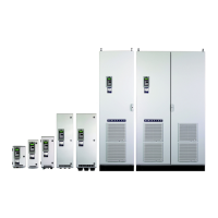
Fig. 21 Variable speed drive in a cabinet on a mounting plate
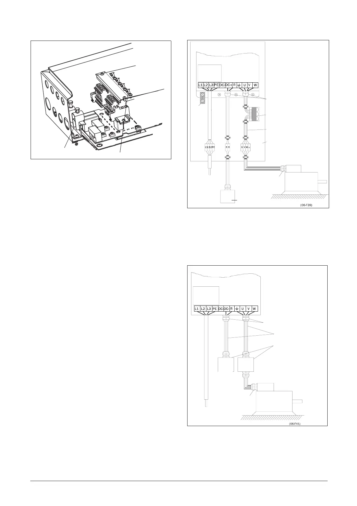
Fig. 22 shows an example when there is no metal mounting
plate used (e.g. if IP54 variable speed drives are used). It is
important to keep the “circuit” closed, by using metal hous-
ing and cable glands.
Fig. 22 Variable speed drive as stand alone
Screening of motor cable
Screening of signal cables
VSD built into cabinet
VSD
RFI-Filter
(option)
Mains
Metal cable glands
Output coil (option)
Screened cables
Unpainted mounting
plate
Metal connector housing
Motor
Metal coupling
nut
Brake resisto
(option)
Mains
(L1,L2,L3,PE)
Litze
Motor
VSD
RFI-Filter
Mains
Metal cable glands
Screened cables
Metal housing
Brake
resistor
(option)
utput
coils
(option)
Metal connector housing
Motor
Metal cable gland
Mains
 Loading...