100 Functional Description Emotron AB 01-4429-01r2
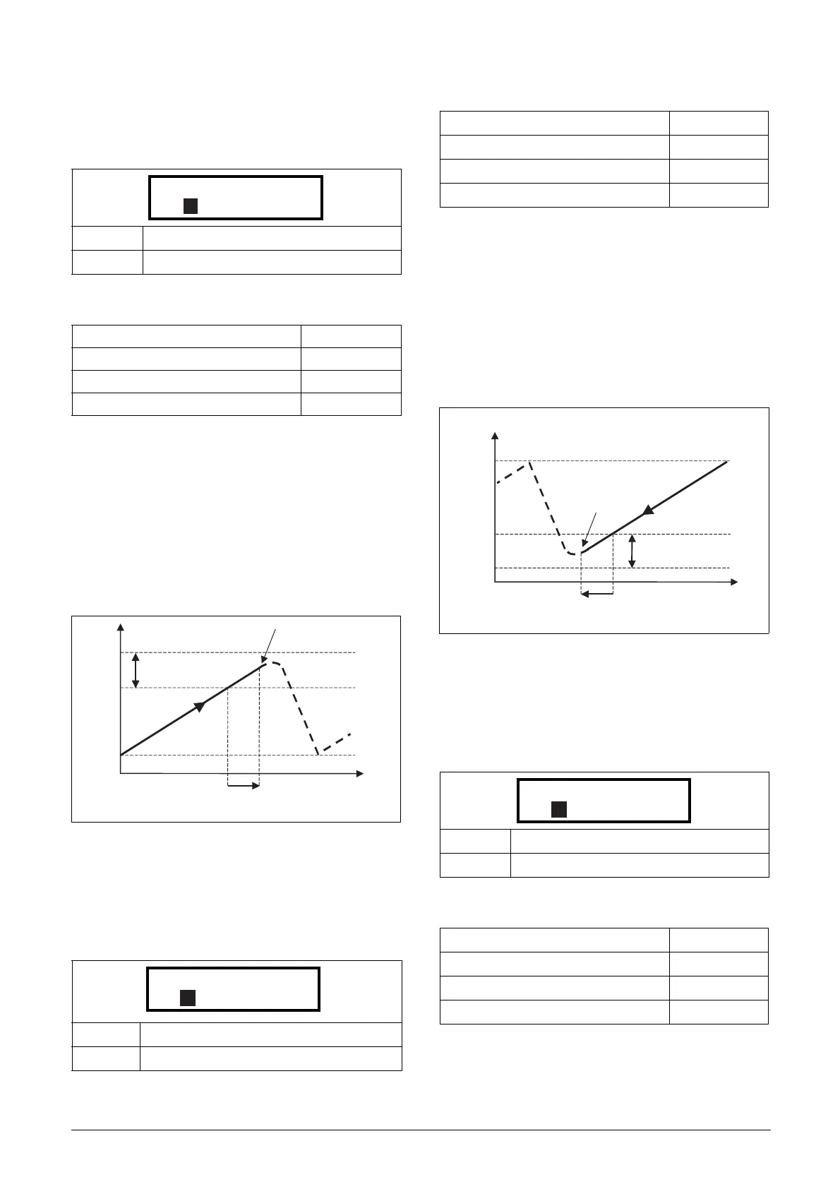
Upper Band [397]
If the speed of the master drive comes into the upper band,
an additional drive will be added after a delay time that is set
in start delay [399].
Communication information
Example:
Max Speed = 1500 rpm
Min Speed = 300 rpm
Upper Band = 10%
Start delay will be activated:
Range = Max Speed to Min Speed = 1500–300 = 1200 rpm
10% of 1200 rpm = 120 rpm
Start level = 1500–120 = 1380 rpm
Fig. 79 Upper band
Lower Band [398]
If the speed of the master drive comes into the lower band
an additional drive will be stopped after a delay time. This
delay time is set in the parameter Stop Delay [39A].
Communication information
Example:
Max Speed = 1500 rpm
Min Speed = 300 rpm
Lower Band = 10%
Stop delay will be activated:
Range = Max Speed - Min Speed = 1500–300 = 1200 rpm
10% of 1200 rpm = 120 rpm
Start level = 300 + 120 = 420 rpm
Fig. 80 Lower band
Start Delay [399]
This delay time must have elapsed before the next pump is
started. A delay time prevents the nervous switching of
pumps.
Communication information
Default: 10%
Range: 0-100% of total min speed to max speed
Modbus Instance no/DeviceNet no: 43167
Profibus slot/index 169/71
Fieldbus format Long, 1=1%
Modbus format EInt
Default: 10%
Range: 0-100% of total min speed to max speed
Flow/Pressure
Speed
Max
Min
Upper band
next pump starts
Start Delay [399]
Modbus Instance no/DeviceNet no: 43168
Profibus slot/index 169/72
Fieldbus format Long, 1=1%
Modbus format EInt
Default: 0 s
Range: 0-999 s
Modbus Instance no/DeviceNet no: 43169
Profibus slot/index 169/73
Fieldbus format Long, 1=1s
Modbus format EInt
Speed
Max
Min
“top” pump stops
Lower band
Stop Delay [39A]
Flow/Pressure

 Loading...


