Emotron AB 01-4429-01r2 Functional Description 113
Subtracting analogue inputs
Example 2: Subtract two signals
Signal on AnIn1 = 8 V
Signal on AnIn2 = 4 V
[511] AnIn1 Function = Process Ref.
[512] AnIn1 Setup = 0-10 V
[5134] AnIn1 Function Min = Min (0 rpm)
[5136] AnIn1 Function Max = Max (1500 rpm)
[5138] AnIn1 Operation = Add+
[514] AnIn2 Function = Process Ref.
[515] AnIn2 Setup = 0-10 V
[5164] AnIn2 Function Min = Min (0 rpm)
[5166] AnIn2 Function Max = Max (1500 rpm)
[5168] AnIn2 Operation = Sub-
Calculation:
AnIn1 = (8-0) / (10-0) x (1500-0) + 0 = 1200 rpm
AnIn2 = (4-0) / (10-0) x (1500-0) + 0 = 600 rpm
The actual process reference will be:
+1200 - 600 = 600 rpm
AnIn1 Setup [512]
The analogue input setup is used to configure the analogue
input in accordance with the signal used that will be con-
nected to the analogue input. With this selection the input
can be determined as current (4-20 mA) or voltage
(0-10 V) controlled input. Other selections are available for
using a threshold (live zero), a bipolar input function, or a
user defined input range. With a bipolar input reference sig-
nal, it is possible to control the motor in two directions. See
Fig. 89.
Communication information
NOTE: The selection of voltage or current input is done
with S1. When the switch is in voltage mode only the
voltage menu items are selectable. With the switch in
current mode only the current menu items are
selectable.
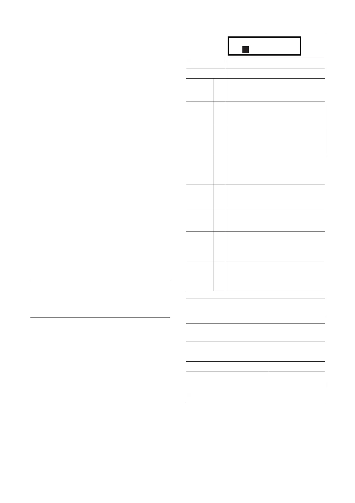
Default: 4-20 mA
Dependent on Setting of switch S1
4–20mA 0
The current input has a fixed threshold
(Live Zero) of 4 mA and controls the full
range for the input signal. See Fig. 91.
0–20mA 1
Normal full current scale configuration of
the input that controls the full range for the
input signal. See Fig. 90.
User mA 2
The scale of the current controlled input,
that controls the full range for the input sig-
nal. Can be defined by the advanced AnIn
Min and AnIn Max menus.
User Bipol
mA
3
Sets the input for a bipolar current input,
where the scale controls the range for the
input signal. Scale can be defined in
advanced menu AnIn Bipol.
0–10V 4
Normal full voltage scale configuration of
the input that controls the full range for the
input signal. See Fig. 90.
2–10V 5
The voltage input has a fixed threshold
(Live Zero) of 2 V and controls the full range
for the input signal. See Fig. 91.
User V 6
The scale of the voltage controlled input,
that controls the full range for the input sig-
nal. Can be defined by the advanced AnIn
Min and AnIn Max menus.
User Bipol
V
7
Sets the input for a bipolar voltage input,
where the scale controls the range for the
input signal. Scale can be defined in
advanced menu AnIn Bipol.
NOTE: For bipol function, input RunR and RunL needs to
be active and Rotation, [219] must be set to “R+L”.
NOTE: Always check the needed set up when the setting
of S1 is changed; selection will not adapt automatically.
Modbus Instance no/DeviceNet no: 43202
Profibus slot/index 169/106
Fieldbus format UInt
Modbus format UInt
512 AnIn1 Setup
Stp 4-20mA

 Loading...


