114 Functional Description Emotron AB 01-4429-01r2
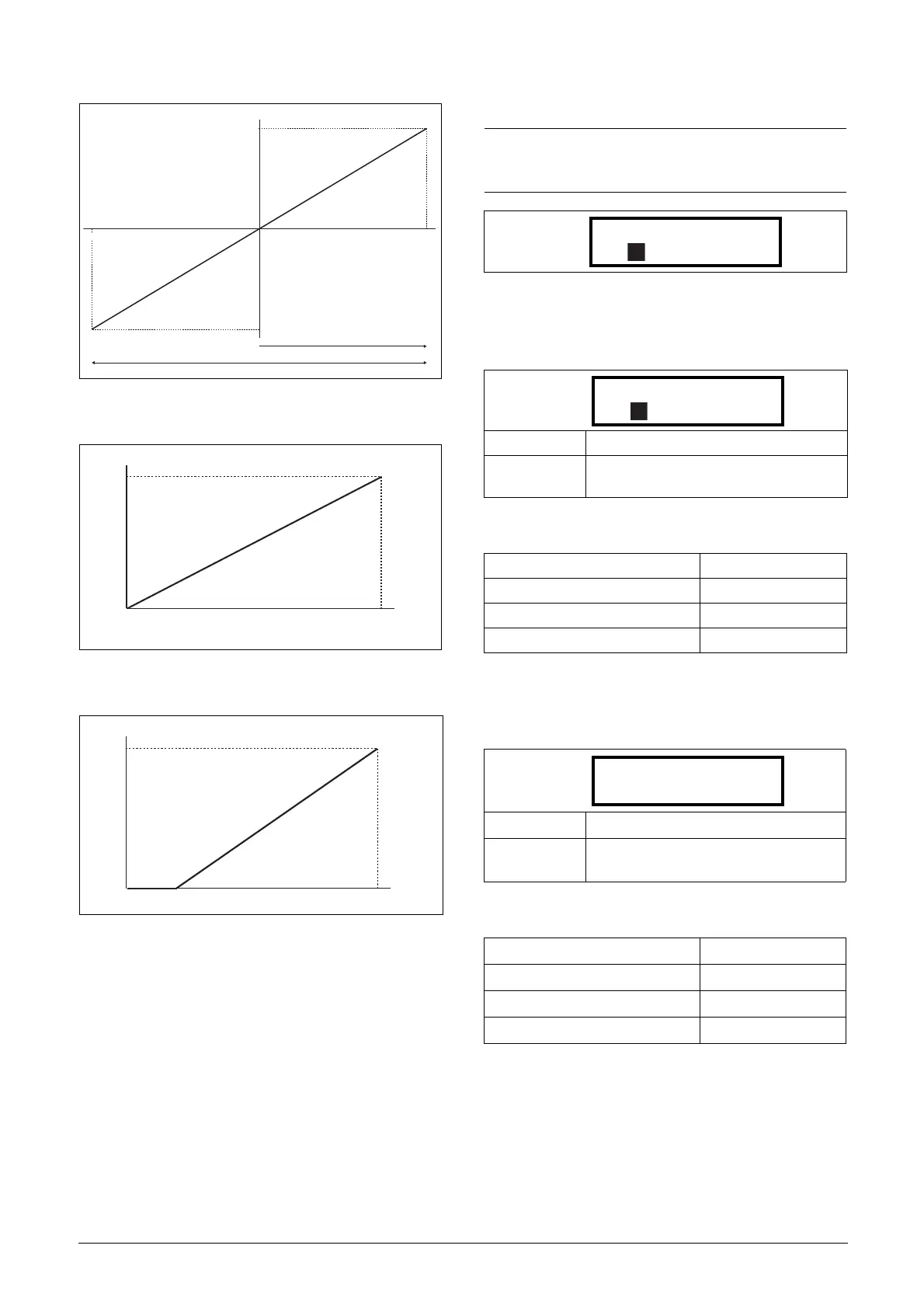
Fig. 89
Fig. 90 Normal full-scale configuration
Fig. 91 2–10 V/4–20 mA (Live Zero)
AnIn1 Advanced [513]
AnIn1 Min [5131]
Parameter to set the minimum value of the external refer-
ence signal. Only visible if [512] = User mA/V.
Communication information
AnIn1 Max [5132]
Parameter to set the maximum value of the external refer-
ence signal. Only visible if [512] = User mA/V.
Communication information
20 mA
100 %
100 %
n
(NG_06-F21)
10 V
0
-10 V
20mA
100 %
n
(NG_06-F21)
0
10 V
NOTE: The different menus will automatically be set to
either “mA” or “V”, based on the selection in AnIn 1
Setup [512].
Default: 0 V/4.00 mA
Range:
0.00–20.00 mA
0–10.00 V
Modbus Instance no/DeviceNet no: 43203
Profibus slot/index 169/107
Fieldbus format Long
Modbus format EInt
Default: 10.00 V/20.00 mA
Range:
0.00–20.00 mA
0–10.00 V
Modbus Instance no/DeviceNet no: 43204
Profibus slot/index 169/108
Fieldbus format Long
Modbus format EInt
5131 AnIn1 Min
Stp 0V/4.00mA
5132 AnIn1 Max
Stp 10.0V/20.00mA

 Loading...


