SS2100i-1 Gas Analyzer
3–18 4900002224 rev. E 12-18-20
7. Connect the alarm output and validation request input wires to the
appropriate terminals, as indicated in Table 3-3 below.
8. Verify that each connection is secure.
9. Close the analyzer enclosure cover according to the procedure under
“To close the analyzer enclosure cover” on page 3-3.
10. To complete the connections, connect the other end of the current
loop wires to a current loop receiver, the serial or Ethernet to a serial
or Ethernet port on a computer, the alarm cables to appropriate
alarm monitors and the validation request input to a switch.
Configuring the RS-232/RS-485 Converter
The Optically Isolated RS-232-to-RS-485 Converter is configured for two-wire
RS-485. DIP switches on the side of the converter, shown in Figure 3–8 on page
3–19, can be used to set time-out and termination, as indicated in Table 3–2
on page 3–17. With the default setting of 9600 baud, the converter will
generally work for baud rates of 9600 and higher.
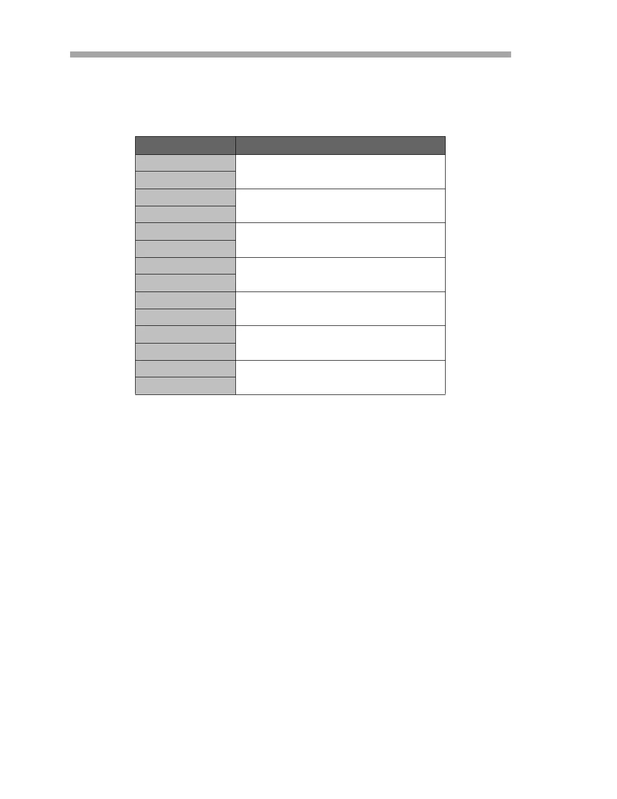
Table 3-3 Terminal block (X3) input/output signal connections
Terminal Description
1
High Concentration Alarm
2
3
General Fault Alarm
4
5
Validation Fail Alarm
6
7
Validation 1 Active
8
9
Validation 2 Active
10
11
Future Use
12
13
Validation Request Input
14

 Loading...


