Introduction
Hardware Installation and Maintenance Manual 1
–17
The relay control board serves as the interface between the analyzer control
electronics and the relays whereas the temperature control board controls the
thermo-electric (TEC) cooler that maintains the laser temperature inside the
sample cell optical head. An optically-isolated RS-232 to RS-422/485 converter
takes the inherent RS-232 serial output of the laser control electronics and
converts it to RS-485.
The auxiliary switch-mode power supply provides power to the heater
temperature controller (located on the bottom level) and the RS-232/RS-485
converter. The power supply is rated for 1.3 A at 24 VDC output at ambient
temperatures T
a
60 ºC. For higher temperatures 60 ºC T
a
70 ºC, the output
power is reduced by 2.5%/ºC. The operational state is indicated by LEDs on the
front face, where green means the output voltage is on and within
specification, and red means the output voltage is on but below specification.
The thermostat in the upper left corner prevents the temperature inside the
enclosure from getting too hot. The thermostat is preset at the factory to open
the heater circuit if the temperature inside the analyzer enclosure exceeds
704 C. The heater circuit will remain open until the manual reset button
(located between the two wire terminals) on the thermostat is pressed or the
temperature drops approximately 30% below the setpoint.
A DIN rail at the bottom of the upper level holds fused terminal blocks, the main
breaker and terminal blocks for all external connections.
On the lower level, the measurement cell is the actual TDLAS spectrometer
through which the gas sample flows. The measurement cell is equipped with a
pressure sensor and thermistor to monitor the thermodynamic conditions of
the sample. A heater maintains the inside of the analyzer enclosure at a
constant temperature and is controlled by the temperature controller via the
solid-state relay.
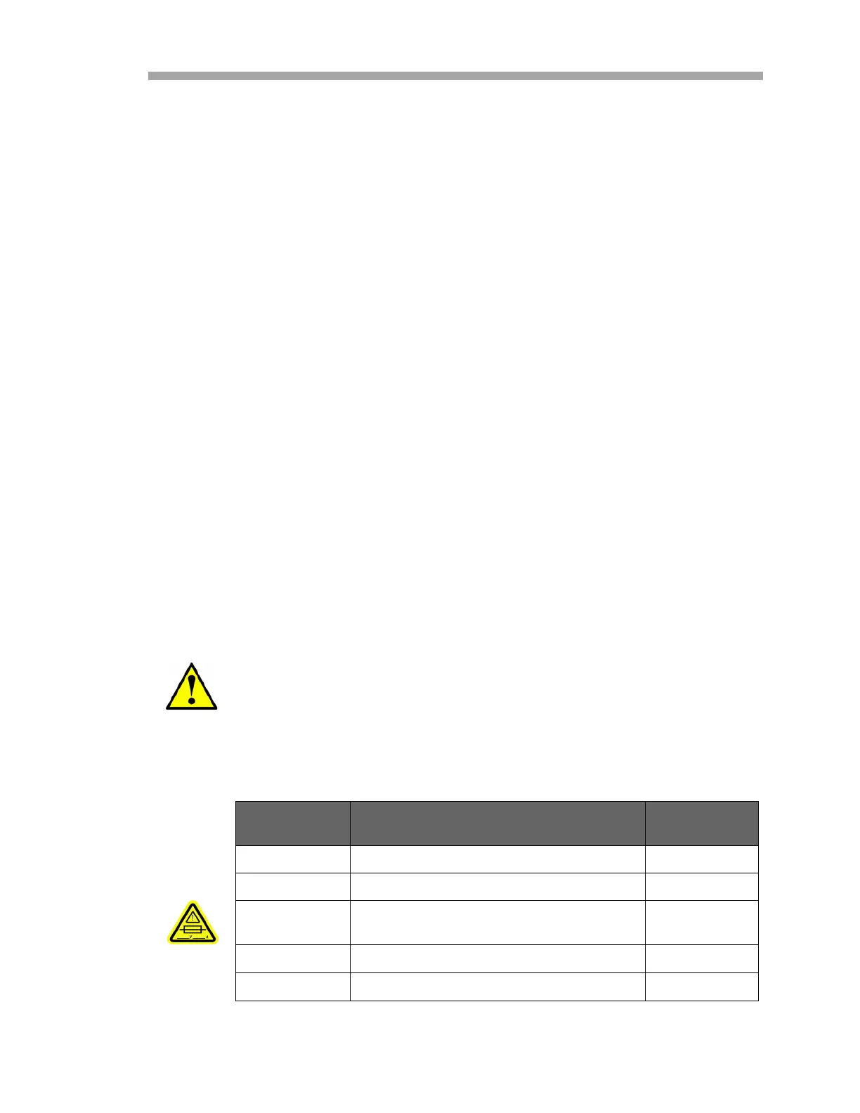
See Figure 1–9 on page 1–13 and to locate fuses. If you need to
replace a fuse, use only the same type and rating of fuse as the
original as listed in Table 1–1 or Table 1–2 on page 1–18. For re-
order part numbers, refer to Table C–2 on page C–5.
Table 1–1 Fuse specifications for 240 VAC systems
Drawing
Reference
Description Rating
F3 Miniature Fuse, 5 x 20 mm, Time Delay
250 VAC/1.6 A
F4
1
1. Housed in fused terminal blocks. Illuminated LED indicates blown fuse.
2. Refer to Figure 1–9 on page 1–13.
Miniature Fuse, 5 x 20 mm, Time Delay
250 VAC/0.5 A
F5
1
,F6
1
,
F7
1
, F8
1
Miniature Fuse, 5 x 20 mm, Time Delay
250 VAC/0.1 A
F9
1
Miniature Fuse, 5 x 20 mm, Time Delay
250 VAC/1.0 A
F10
1
Miniature Fuse, 5 x 20 mm, Time Delay
250 VAC/1.2 A

 Loading...


