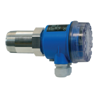
SS2100i-1 Gas Analyzer
3–12 4900002224 rev. E 12-18-20
Toconnectelectricalpowertotheanalyzer
1. Open the analyzer enclosure cover according to the procedure under
“To open the analyzer enclosure cover” on page 3-3 to gain
access to the field interface terminal block.
2. Install an appropriate compound barrier seal gland per
manufacturing instructions provided with the gland into the M20
access port on the bottom left of the enclosure. Refer to
“Application of gland lubricant” on page 3-15.
3. Run cable from the power distribution panel to the gland.
4. Pull ground, neutral and hot wires (1.5 mm
2
, #14 AWG minimum)
into the analyzer enclosure.
An approved switch or circuit breaker rated for 15 amps should be
used and clearly marked as the disconnecting device for the
analyzer.
Because the breaker in the power distribution panel or switch will
be the primary means of disconnecting the power from the
analyzer, the power distribution panel or switch should be located
in close proximity to the equipment and within easy reach of the
operator.
Figure 3–5 Enclosure door - inside view
GROUND
CONNECTION

 Loading...


