Maintenance & Troubleshooting
Hardware Installation and Maintenance Manual B
–17
10. Remove excess seal tape from the ‘T’ junction.
11. Check for tape fragments inside the ‘T’ junction and remove with a
pick.
12. Remove the new pressure sensor from the packaging. Retain the
black connector cap on the sensor to protect the pins - do not
remove the cap.
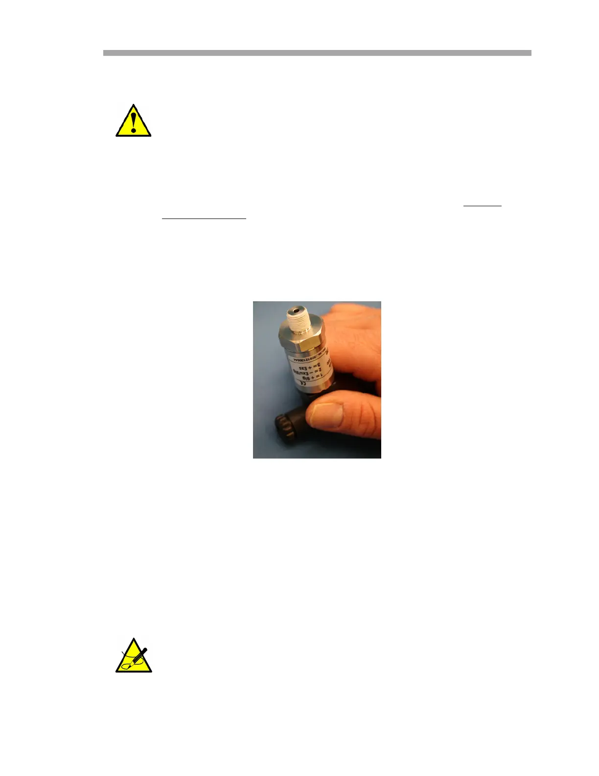
13. Wrap stainless steel PTFE tape around the threads at the top of the
pressure sensor, beginning from the base of the threads to the top,
approximately three times taking care to avoid covering the top
opening. Refer to Figure B–11 below.
14. Insert the new pressure sensor onto the ‘T’ junction.
15. Hand tighten the pressure sensor clockwise on the ‘T’ junction until
it is no longer moving freely.
16. Turn the sensor clockwise with a 7/8” or adjustable wrench until
tight. Two or three threads on the pressure sensor should still be
visible.
17. Remove the black harness cap from the pressure sensor and discard.
Threads at the ‘T’ junction showing signs of galling indicate a
possible leak. Refer to “Service Contact” on page B-27 to
arrange for repair.
If a new cable is required, do not discard the new harness cap.
Connect the new harness/cable to the new pressure sensor.
Figure B–11 Replacing seal tape

 Loading...


