SS2100i-1 Gas Analyzer
1–10 4900002224 rev. E 12-18-20
On the front cover, the keypad and LCD display serve as the user interface to
the analyzer. Power and signal connections are made via access ports on the
bottom of the analyzer. Tube fittings on the right side are for sample supply and
return connections. Four sturdy feet on the back of the enclosure serve as
attachment points for mounting the analyzer.
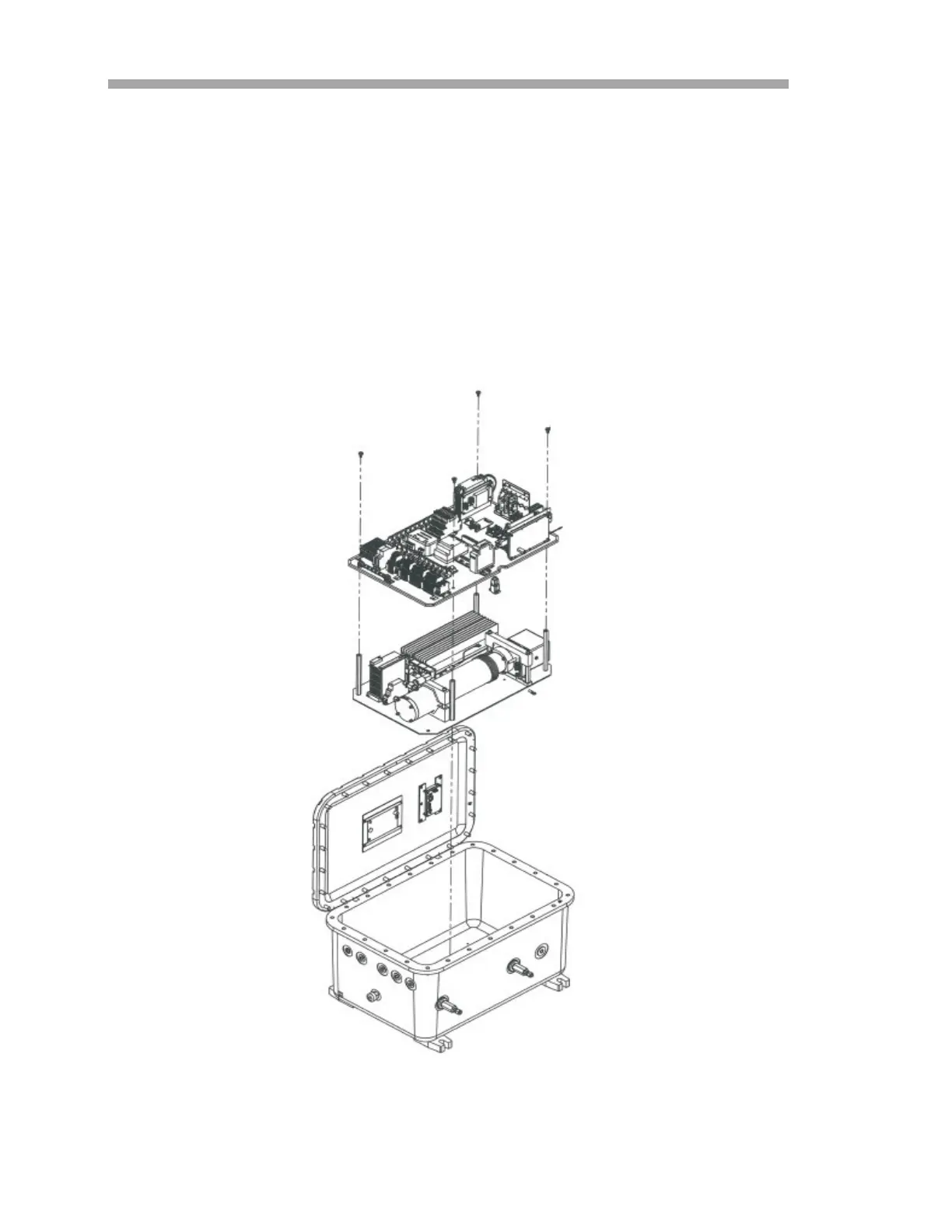
The upper and lower levels for the analyzer are shown in Figure 1–6 (8/28 m
sample cell), Figure 1–7 on page 1–11 (0.8 m sample cell) or Figure 1–8 on
page 1–12 (0.1 m sample cell). The top level is the electronics panel assembly,
shown in Figure 1–9 on page 1–13, The lower level is the sample cell panel
assembly shown in Figure 1–10 on page 1–14 (8/28 m sample cell), Figure
1–11 on page 1–15 (0.8 m sample cell) or Figure 1–12 on page 1–16 (0.1 m
sample cell).
Figure 1–6 Upper and lower levels of analyzer
assembly (8/28 m sample cell)

 Loading...


