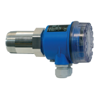
SS2100i-1 Gas Analyzer
3–20 4900002224 rev. E 12-18-20
Connecting the Gas Lines
Once you have verified that the analyzer is properly wired, you are ready to
connect the sample supply and sample return lines. All work should be
performed by technicians qualified in pneumatic tubing.
SpectraSensors recommends using 1/4” O.D. x 0.035” wall thickness,
seamless stainless steel tubing. If the analyzer comes with a factory installed
sample system, consult the system drawings for tubing sizes and attachment
points.
Toconnectthesamplesupplyandreturnlines
1. Connect the supply and return tubes to the analyzer using the
stainless steel compression-type fittings provided.
2. Tighten all new fittings 1-1/4 turns with a wrench from finger tight.
For connections with previously swaged ferrules, thread the nut to
the previously pulled up position, then tighten slightly with a wrench.
Secure tubing to appropriate structural supports as required.
3. Check all connections for gas leaks.
Changing the 4-20 mA Current Loop Mode
By default, the 4-20 mA current loop output is factory set to source current. In
some instances it may be necessary to change the 4-20 mA current loop output
in the field from source to sink. The work should be performed by personnel
qualified in electronics assembly.
For systems with integrated sample conditioning systems, refer to
the Sample Conditioning System (SCS) Manual.
Do not exceed 10 PSIG (0.7 barg) in sample cell. Damage to cell
may result.
Changing the current loop mode may negate specific hazardous
area certifications. Contact Service for details. Refer to “Service
Contact” on page B-27.
Hazardous voltage and risk of electric shock. Turn off and
lock out system power before opening the electronics enclosure
and servicing.

 Loading...


