SS2100i-1 Gas Analyzer
3–10 4900002224 rev. E 12-18-20
5. Verify that each connection is secure.
6. Close the analyzer enclosure cover according to the procedure under
“To close the analyzer enclosure cover” on page 3-3.
Connecting Electrical Power to the Analyzer
The analyzer will be configured for 120 or 240 VAC at 50/60 Hz single phase
input. Refer to the electrical schematics in Appendix D for field wiring
terminations. All work should be performed by personnel qualified in electrical
installation.
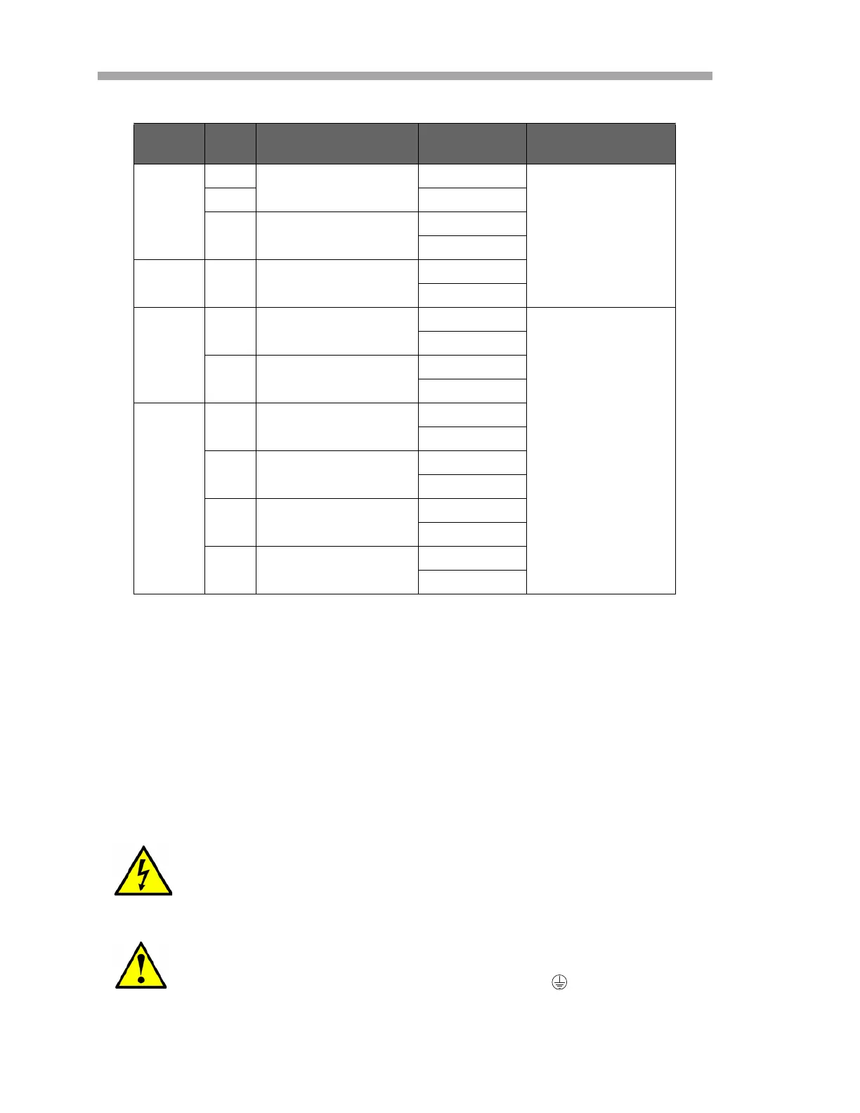
Table 3–1 Terminal block (X2) solenoid valve connections
Figure SOV Description Terminal
Relay Rating
I
th
3–1
S1
Scrubber Solenoid
1
6 A
S2 2
- No Connection
3
4
3–2 S1 Scrubber Solenoid
1
2
3–3
S1 Scrubber Solenoid
1
6 A
2
S2 Val 1 Solenoid
5
6
3–4
S1 Scrubber Solenoid
1
2
S2 Main/Val Solenoid
3
4
S3 Val 1 Solenoid
5
6
S4 Val 2 Solenoid
7
8
Hazardous voltage and risk of electric shock. Turn off and
lock out system power before opening the electronics enclosure
and making any connections.
Careful consideration should be taken when grounding. Properly
ground the unit by connecting the ground lead to the ground bus
bar in the system labeled with the ground symbol .

 Loading...


